Assembling a 4s LFP battery
- Confidence
- ●○○○○
- Domain experience
- ●○○○○
- Audience
- People worried about the electrical grid
- Summary
- I put my ideas to the test by building a small 4s1p battery.
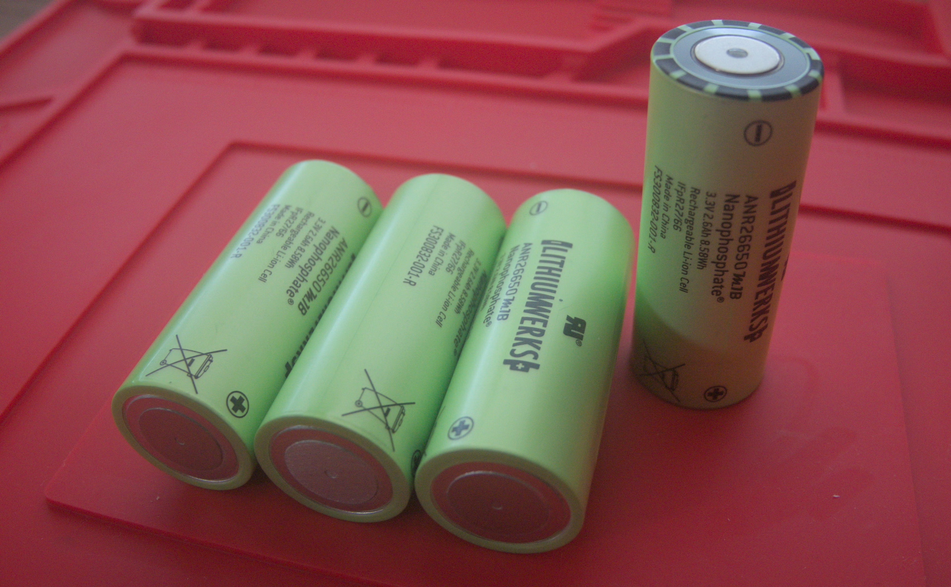
With a functioning spot welder in hand, I set out to build a battery with Lithium Werks ANR26650M1B cells. These are LFP cells nominally at 3.3 V with a capacity of 2500 A·h.
Design
Since this battery is going into a 1:6 scale RC tractor, I have some operational constraints. First, I’m going to try to fool a Hobbywing QuicRun 1080 G2 ESC into believing it’s running with power from a LiPo. This ESC supports 2s and 3s LiPo batteries, which means it should operate between 6.4 V and 12.6 V. A 3s LFP configuration will give us a usable range of 7.5 V to 11 V; for 4s, 10 V to 14.8 V.
In general, a 4s LFP battery is going to be more useful than a 3s one, simply because 12 V nominal circuits are more common. I suspect I can get away with a 4s pack here as the electronics in the ESC should be relatively simple. I hope the worst case is that I might fry the BEC components, which would force me to use an external BEC instead.
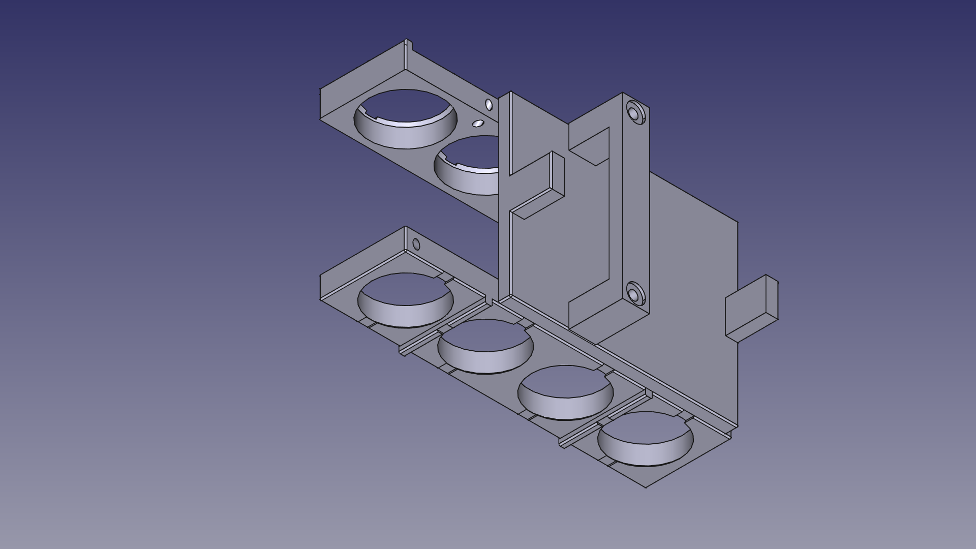
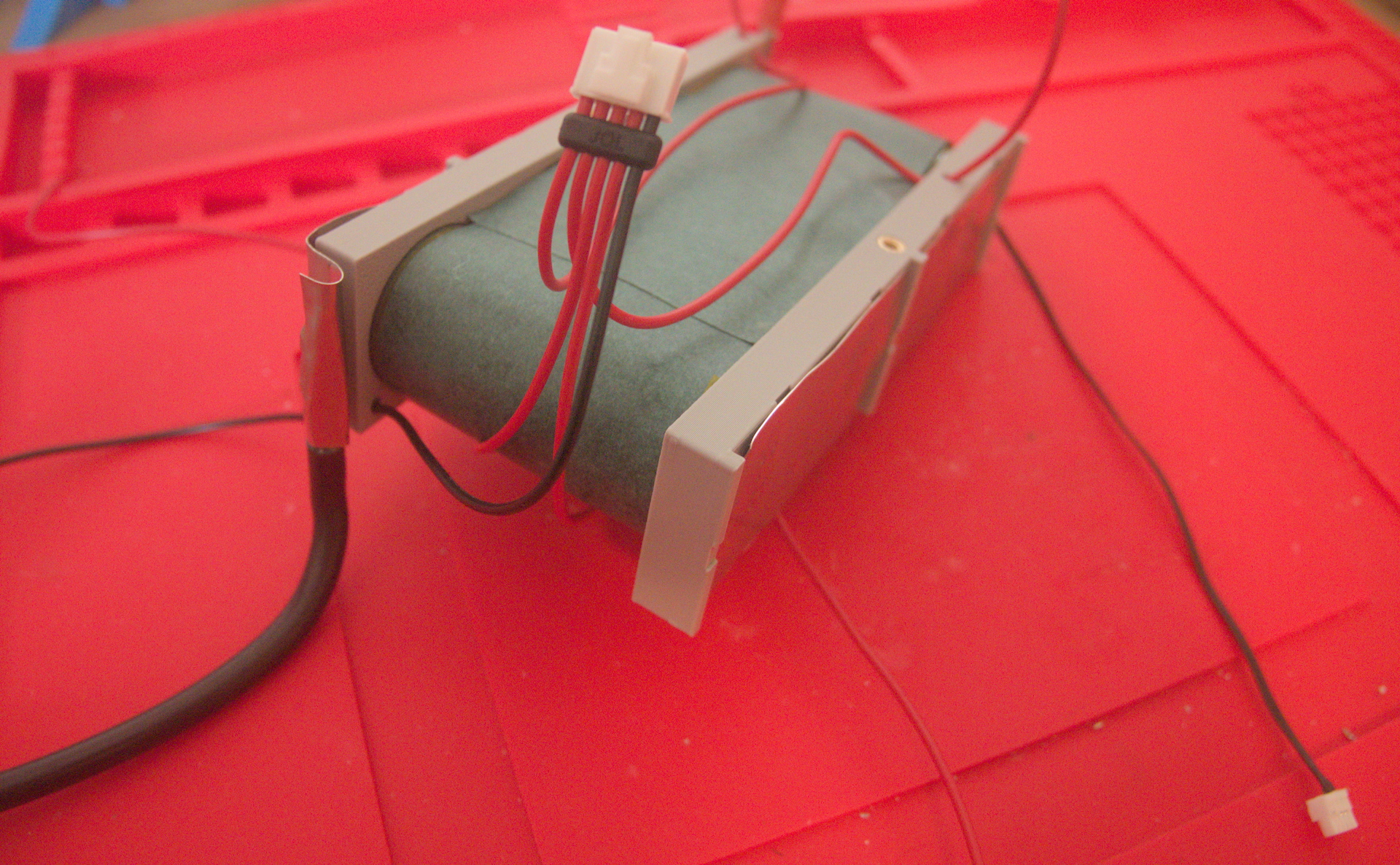
The other constraint is size. This battery has to fit under a hood that is only 77 mm wide on a platform that limits its height to about 45 mm, so there isn’t a ton of room for wires or even the BMS. Initially, I wanted to have two cells on top of two cells (so the axial orientation would look like a square), but since I had more length than height to work with, I opted to make it inline:
Safety
Since we’re using a BMS, our first step is to synchronize the cell voltages. A BMS won’t work at all if the voltages of individual cells are too far apart: it assumes some of the cells have been damaged. Since cells ship at a low SoC, I generally just pick a voltage above their current charge level and let them all charge up to that point. Then I double check everything with a voltmeter.
I won’t do a full charge until they’re in the battery as I’d rather spot weld mostly discharged cells.
Two materials are usually used to limit the risk of short circuits: adhesive-backed fishpaper and Kapton tape. We use the thicker fishpaper for separating electrodes and Kapton tape to hold the fishpaper (which seems to have a rather weak adhesive) and other electrically isolated components in place.
For most cylindrical cells, the entire housing is the anode, and the cathode protrudes on one side, separated by a thin layer of plastic insulation. (For the ANR26650M1B, the housing is the cathode, but it is otherwise structurally similar.) To protect the plastic insulation, we use a fishpaper gasket matched to the cell diameter.
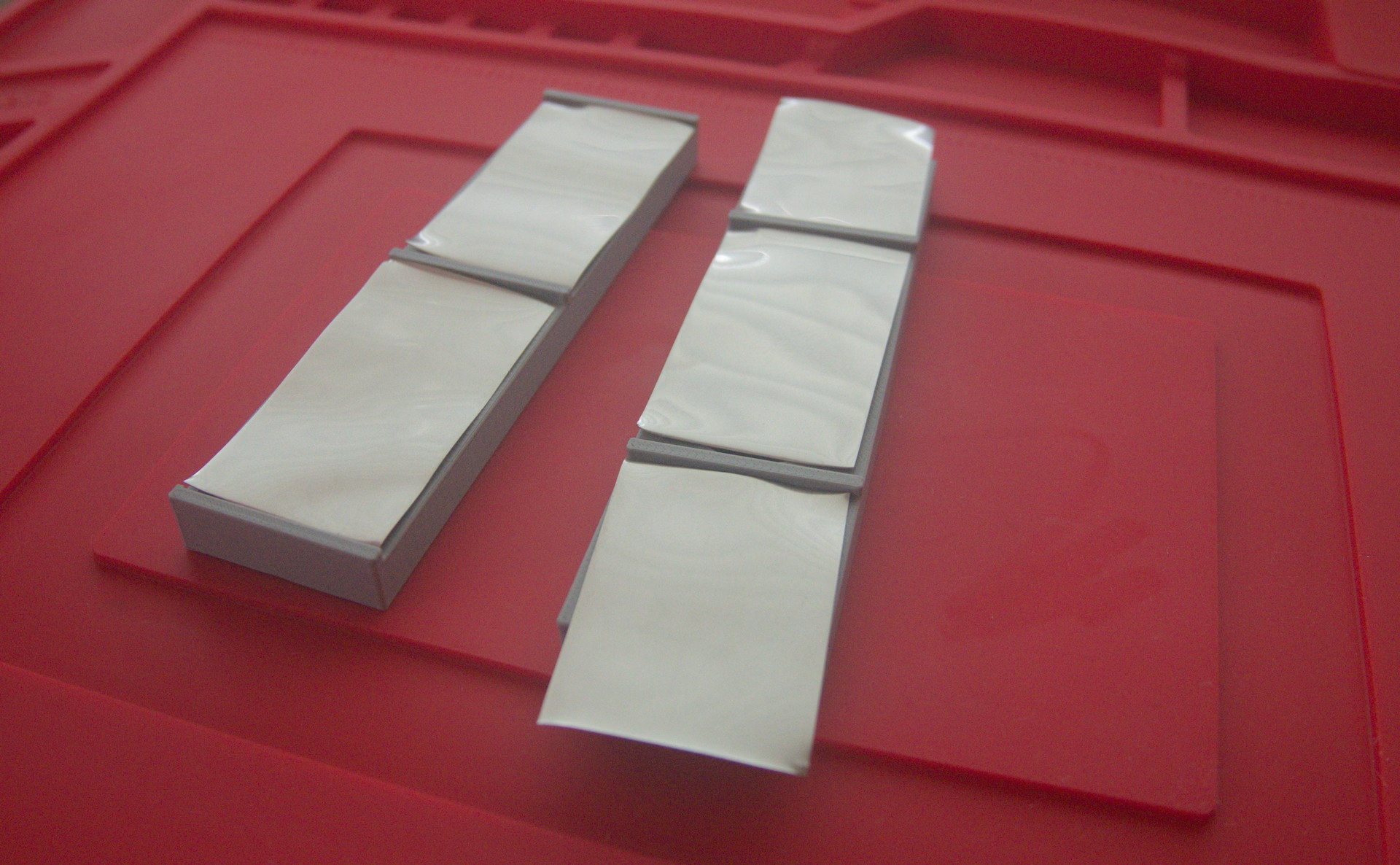
Likewise, we want to protect each parallel group from each other. To do that, we wrap the housings of the entire group in fishpaper after assembling them, leaving only the electrodes exposed. Once the groups are assembled in series, we can additionally wrap them, leaving only a small area exposed for attaching the balance wires. With the 1p battery I’m building, I’m going to put a layer of fishpaper over each cell.
We’ll also use fishpaper anywhere wires cross each other, around the area the BMS overlays the cells, and whenever nickel strips or wire are near cell housings.
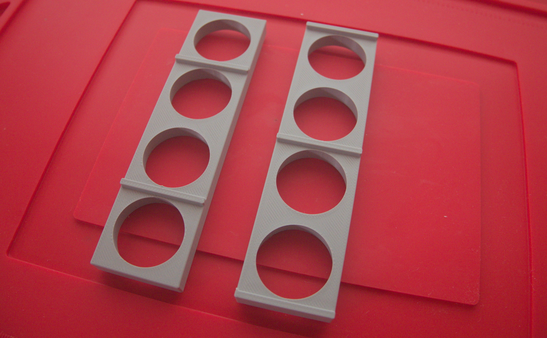
To aid in heat dissipation and reduce the risk of a single malfunction propagating to adjacent cells, it’s usually a good idea to physically separate cells from each other unless size constraints prevent it. You can buy general-purpose plastic spacers, but I decided to 3D print a model specific to this battery. It has raised areas between each series connection. These serve both as additional short-circuit protections and as build guides. The overall width of my spacers is just over 30 mm, which means I can lay my nickel strips directly on top of the cells without worrying about wrapping them around the cell housings.
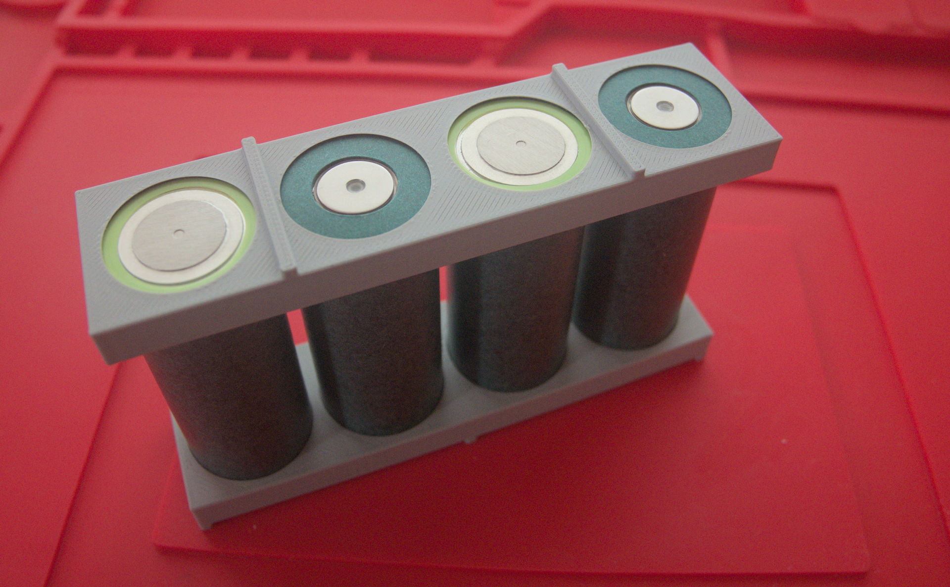
Finally, many people like to round off the (potentially quite sharp) edges of the nickel strips before welding them to prevent them from potentially digging into the fishpaper and eventually shorting the cell housing. This isn’t necessary with my cell spacer design.
Preparing the nickel strips and lead wires
I had a really, really hard time figuring out how to attach the battery leads, which are 10 AWG wires, to the nickel strips. Even though I derated my overall design to 25 A, I have a 60 A BMS: better safe than sorry for everything in front of it, I guess. Anyway, everyone just says “solder them”—well, easier said than done!
I’m using a Hakko FX-888D, which has plenty of power (you’ll need it), a 3.2 mm chisel tip, high quality eutectic solder, and RMA flux paste. I wouldn’t skimp on any of the materials, personally. It’s hard to get enough heat into the chonky nickel strip.
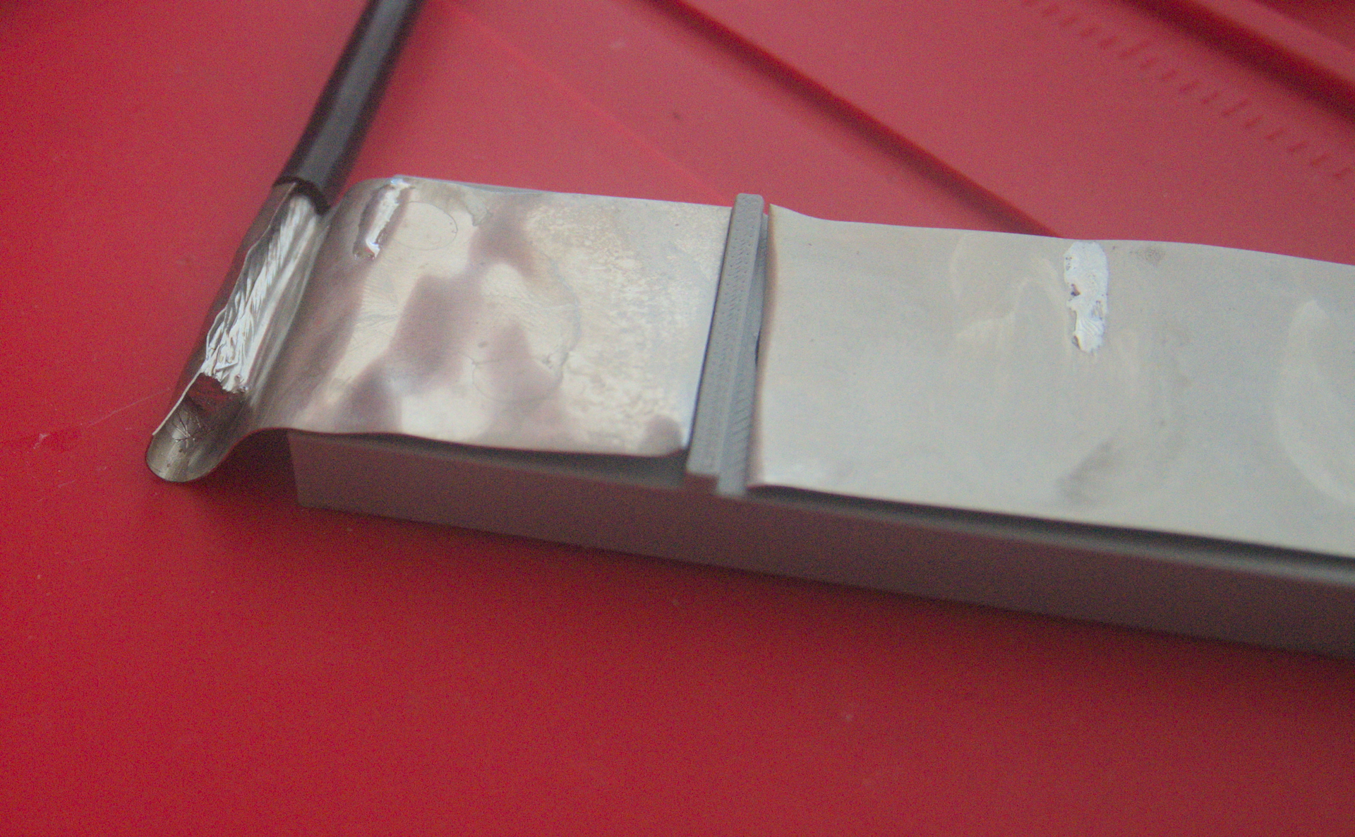
I started by tinning the wire and the area of a “pad” I wanted to create on the nickel strip. The solder did not stick well to the nickel, even when cleaned with IPA. I had to scratch up the surface using some medium-grit sandpaper and apply a liberal amount of flux to the area. (I also used a lot of flux on the wire itself.)
To hold everything in place, I put the strip in my vise and aligned the wire using a helping hand. Even so, I found it very difficult to get the solder to flow properly. I probably tried 5–10 different approaches (varying temperature, amount of flux, etc.) in this vein before I went back to the drawing board (that is, searching the internet for clues).
The most useful tip I found was to fold and crimp the nickel over the wire before soldering. In practice, this made it difficult to tell when the solder had filled the gaps inside the fold, and I also had trouble orienting the iron to get consistent heating, so I ended up with a slightly modified pattern: making a semicircular cup around the wire and filling it in, similar to how you’d attach a wire to any other soldered connector. I lightly pressed the nickel into the wire with pliers. Then I was able to wedge the iron into the cup on one side and feed solder from the other.
My final revelation was to significantly increase the temperature for this step. I initially tinned the wire and metal strip at around 375 °C, but I bumped my iron up to 415 °C to make the connection. (And it still took an awkwardly long time.)
I also tinned the locations on the nickel strip where I plan to attach the BMS balance wires. These wires are very small and shouldn’t take much time to solder, but I figured I’d get everything ready as long as I had my iron out.
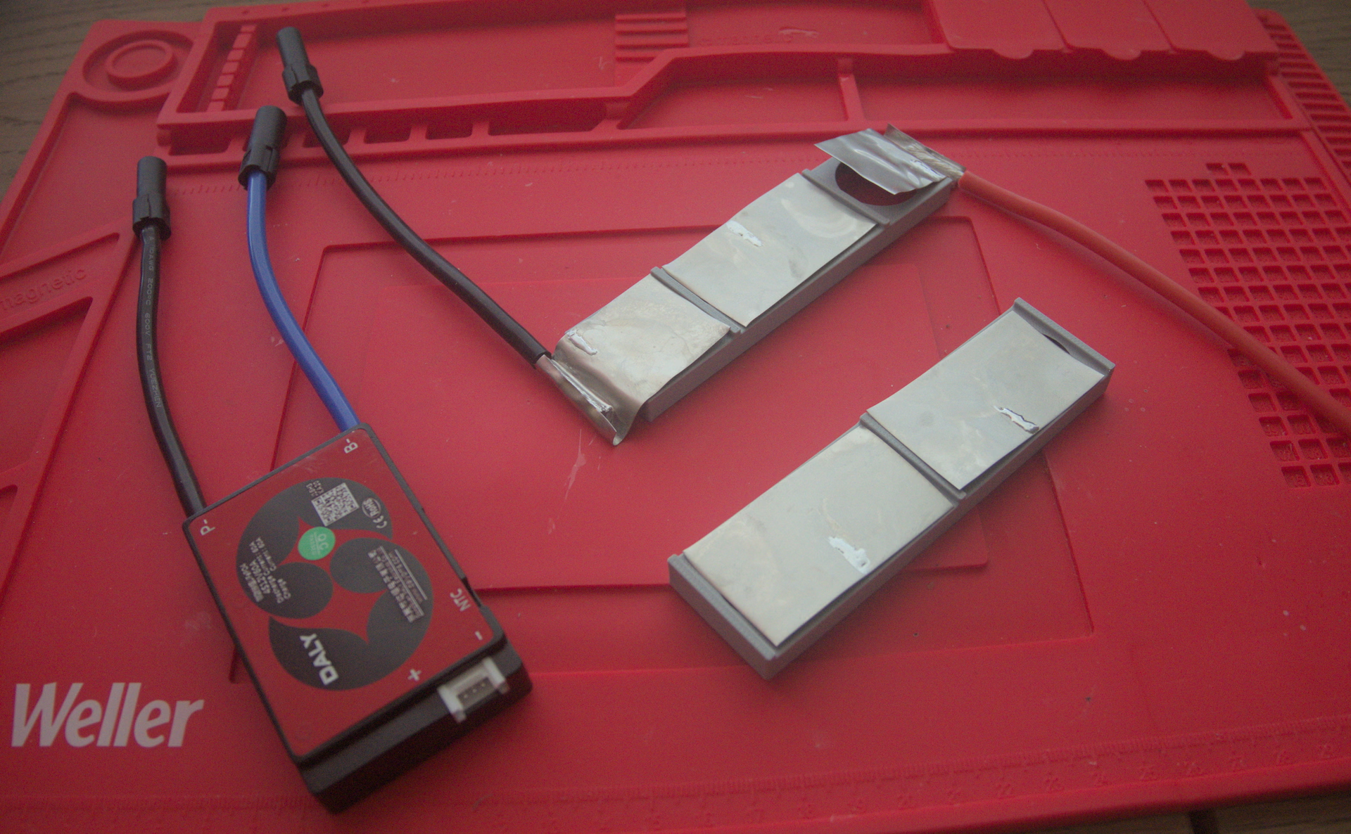
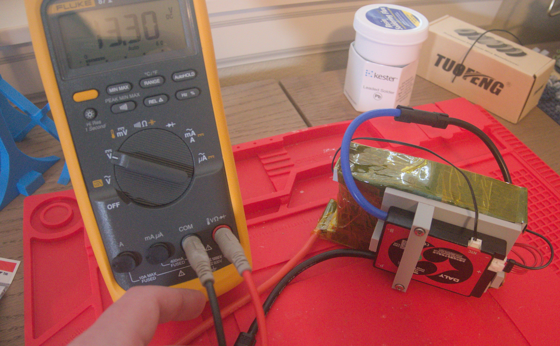
Most of the time, a BMS is integrated into either a battery itself (“protected”) or part of the control circuitry for the product that uses the battery. I bought a DALY BMS to attach to the battery, but I don’t really want it wrapped into the battery itself or soldered directly to the battery terminals. In my mind, the failure modes and lifespan for the cells and the BMS seem distinct, so they should be separate parts.
To connect the BMS to the negative battery lead, I’m using Amass XT150s, which are single-pole connectors that can handle up to 100 A continuously over 8 AWG wire. The DALY BMS also has terminal housings for its balance and thermistor wires, so the whole unit should be swappable with only minor inconvenience.
To connect to the load, I also opted to use XT150s, mostly for their single-pole design, which allows me to continue to keep the BMS and cells physically separated. Also, with an XT150, I should be able to split the load side out into four 14 AWG wires (equivalent to about 8 AWG, using the total coss-sectional area of the wires) to connect to the ESC, charger, or anything else I want to power.
Power sources are always attached to the female connector for safety reasons (it’s harder to accidentally short a female connector, which is usually fully obscured by its housing), so I went ahead and soldered them onto my positive lead wire, negative lead wire, and the load side of the BMS. I also soldered a male connector to the battery side of the BMS.
XT150 connectors can be a bit difficult to manipulate. Here’s what I learned:
- The female connector goes in the smaller housing.
- It’s easiest to push the housing over the connector while it’s still hot, within a minute or so after soldering.
- If the housing gets stuck and won’t budge, I actually had success spraying into it with a bit of IPA to temporarily lubricate it, as unintuitive as that sounds.
- The housing needs to click over the connector. Until it clicks, it can still be pulled back with significant enough force.
Cell spacer improvements
With my cell spacer design, the 30 mm-wide nickel strips completely obscure the cell contacts, so it’s annoying (or dangerous, depending on your perspective) to align the spot welder electrodes in the right place. I added small notches to help with visual orientation. I also could have used a Sharpie, but I was going to reprint the spacer anyway, so I figured I’d make it precise.
A more significant change is adding some routing guides for the BMS balance wires. It’s important to prevent the balance wires from crossing over each other or the lead wires because friction during movement could wear the insulation, eventually leading to a short circuit. I think this is actually easier to manage with larger packs because you simply have more surface area at your disposal; either way, this particular approach unfortunately doesn’t scale to a different pack design, but I do like it for an inline configuration.
I also decided to add a bracket for holding the BMS. This necessitated a few holes for heat set inserts in the spacers.
Finally, late in the process I discovered the way the ANR26650M1B cells vent is by splitting the can on the positive electrode. According to their design documents, this requires 1 mm of space available at the edge of the cell, which I hadn’t accounted for.
Spot welding woes
I was making the changes to the cell spacer design, but it happened to be an unusually nice March evening in Portland, so I took my kWeld outside and started playing with one of the cells instead. My goal was to dial in the energy required to spot weld the pack, which I expected to be around 30 J for the negative electrode and 40 J for the positive electrode.
Frustratingly, the positive electrode simply would not make a reliable weld nugget. Why? Why?! Well, the ANR26650M1B can is actually made of aluminum with a small 0.2 mm-thick pure nickel disc laminated to the end. It dissipates heat extremely efficiently, which meant I needed to push more current than a single kCap unit could provide. (I tried up to 150 J, but the time scaled with the current, so the instantaneous heat transfer remained the same.)
I mulled over some options:
- Import another kCap module from Canada and run them in parallel. This would get the kWeld up to about 1700 A, which would be pretty neat and I’m sure it would work, but it’s also a rather expensive option, considering I still didn’t have even a simple functional battery at this point.
- Disassemble the kWeld, buy a lead-acid starter battery (or LiPo), and try to use it that way. Also expensive and annoying to boot.
- Try 0.15 mm-thick nickel strips instead. No guarantee I’d fare any better (although I suspect I would). I’d have to increase the width to 40 mm to carry the same current.
- Try another cell model that doesn’t have the same can design. Assuming I can locate one with a more traditional nickel-plated or stainless steel can, I should be able to successfully weld to it.
I haven’t found a good source for 40 mm-wide nickel strip (should I be buying sheets and cutting them myself?), so I started looking for alternative cells. The closest one may be the Vapcell IFR26650. My understanding is Vapcell rewraps large Chinese manufacturers’ cells to sell to consumers, and there are no real datasheets or design guidelines to go off of for this cell, so we’re more or less taking a gamble they will be drop-in replacements for the ANR26650M1B. But they seem to perform adequately, they have a reputation for maintaining their capacity for a lot of cycles, and they’re widely available domestically, so I’m going to give them a try.
Once I have a working battery and a better understanding of the entire process, I’ll probably buy a second kCap to finish making packs with my ANR26650M1B cells.
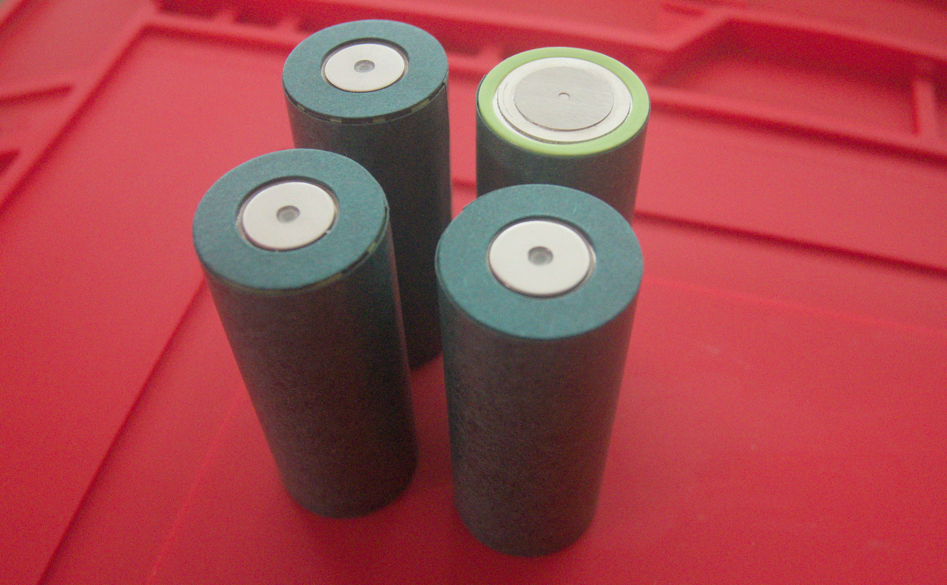
Spot welding Vapcell IFR26650 cells
The Vapcell IFR26650 cells I received were marginally larger than their Lithium Werks cousins, and while they fit in the spacer I designed, I felt they were now way too snug, so I decided to increase the diameter by about 0.5 mm. These cells seemed to have a more conventional mechanism for venting through their cathodes so I wasn’t as concerned about that problem; I just wanted a good fit that didn’t exert any force on the cell housings.
I was able to successfully spot weld 0.2 mm-thick nickel to the cathodes of these cells at 60 J and the anodes at 70 J. Feeling out the quality of the welds is a bit of an art. To create a good weld, you seem to need to apply a little bit of pressure, but not a lot, to the joint. The electrodes of the kWeld should be close to each other and positioned at somewhere between a 30 ° and 45 ° angle apart. Aside from pulling on the nickel strip, the most reliable proxy for quality I’ve found is the resistance value given by the kWeld in its post-weld readout. For this cell, it seems like a value around 0.8 mΩ–0.9 mΩ is ideal. Higher values indicate a poorer weld, and anything over about 1.2 mΩ probably isn’t usable.

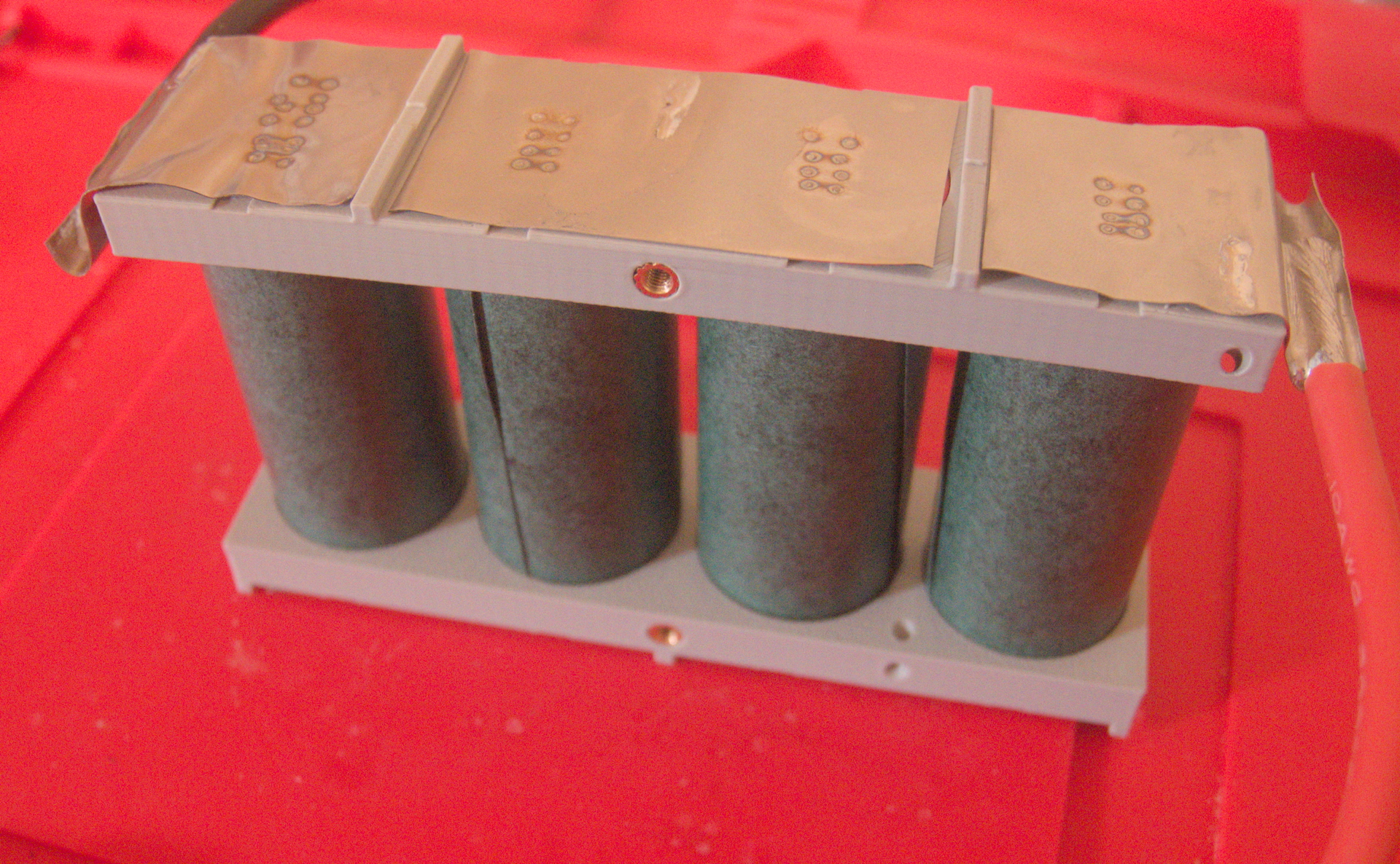
Making the series connections
After I printed my updated cell holder design, I made sure everything looked good before welding the “production” cells.
Welding the cells was fairly uneventful. I went in order of the series (that is, I flipped the assembly over after I attached each nickel strip to a cell) and double-checked voltages and internal resistance as I went. These cells had an internal resistance around 4 mΩ–5 mΩ each and I charged them up to about 3.35 V.
I had a mental checklist for each connection I made (which I have reproduced here anyway, so I should have just written down in the first place, but I digress):
- Set the kWeld to the proper energy, either 60 J or 70 J depending on whether we’re welding to the cathode or anode, respectively.
- Position the electrodes using the guides in the cell holder. Make sure the angle is good. I put a little torque on them because I felt it made it easier to apply consistent pressure as I clearly favor my right hand otherwise.
- Weld the cells. Leave the foot pedal engaged after each weld to make sure the resistance was less than about 1.2 mΩ. Aim for at least two and ideally three very high quality welds per connection.
- Check the voltage of the entire battery so far and make sure it adds up correctly.
- Check the internal resistance of the entire battery using a microohmmeter and make sure it isn’t getting too out of whack.
- Flip the battery over and repeat.
Wrapping everything up
Before we start layering tape over everything that shouldn’t be exposed, we need to make sure the thermistor is in a practically useful place for the BMS to be able to detect overheating. I decided to put it roughly in the enclosed area between two cells, although I also considered taping it directly to one of the terminals. (The way I chose felt a little cleaner, but I think in theory it might take slightly longer to trip the BMS if something goes wrong.)
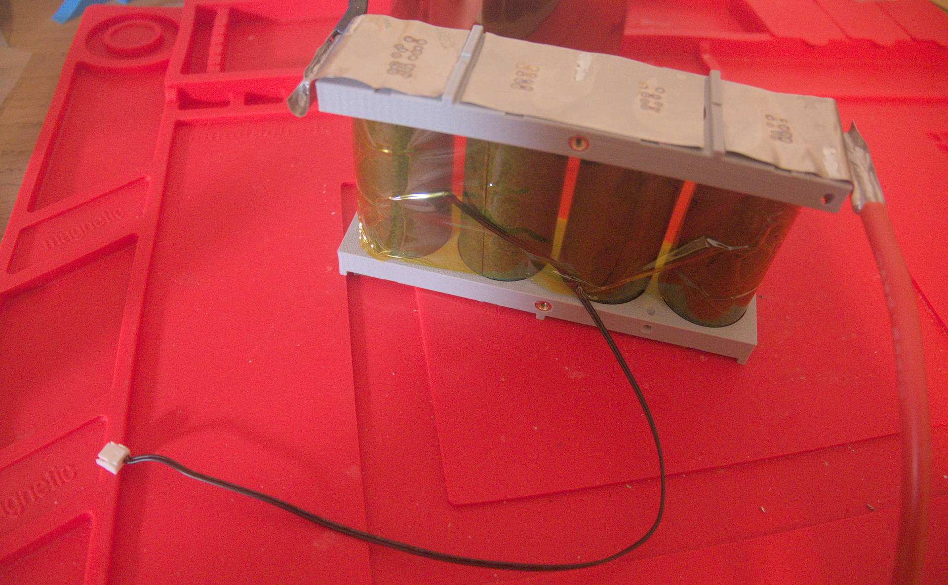
To connect the balance wires, I first routed them through their respective guide holes. I was happy the other end was already assembled in a housing because I didn’t have to worry about shorts. I made them fairly taut because I’m going to back them out a bit once I strip and solder them. With the tinned pads on the nickel strips, it took less than a second to solder each wire, so I have no concerns about excess heat affecting the cells.
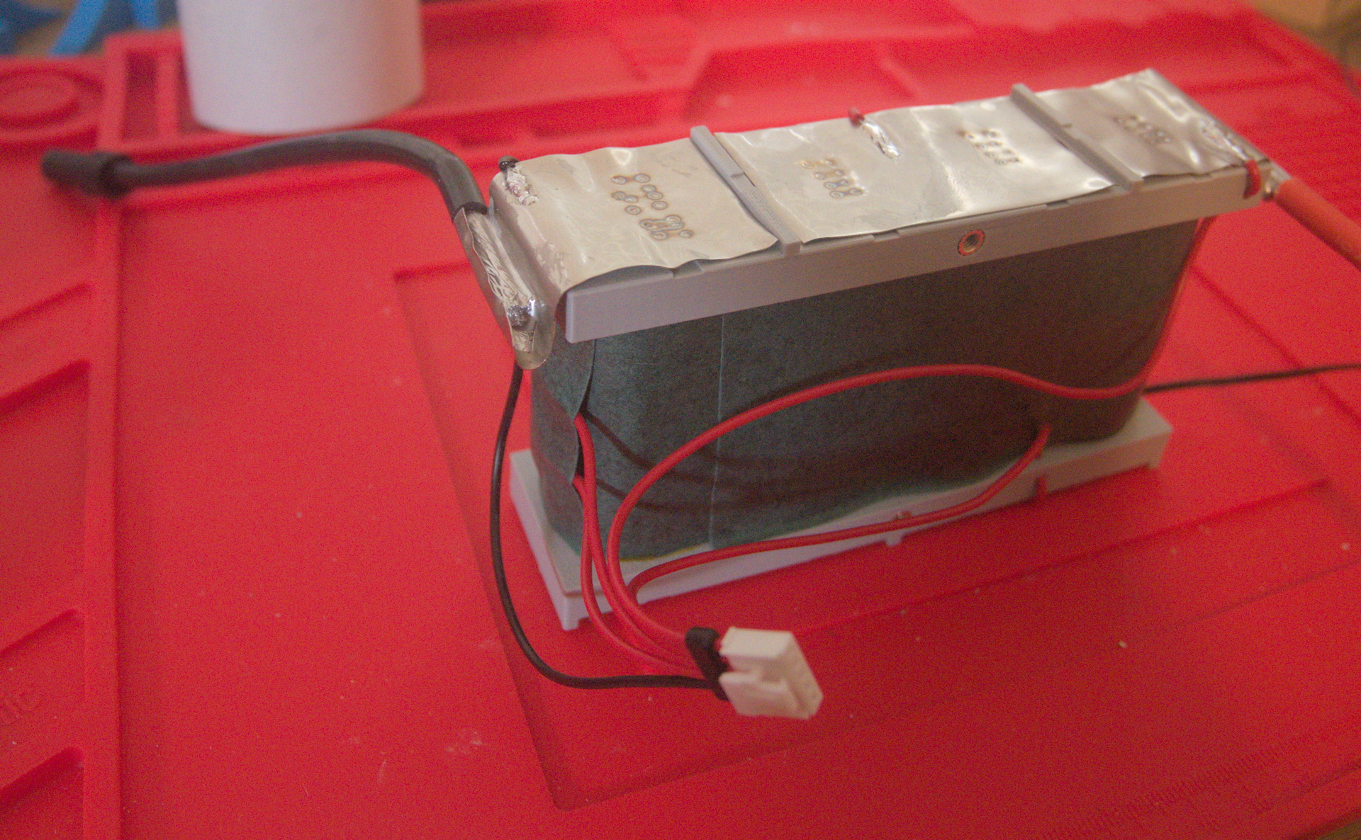
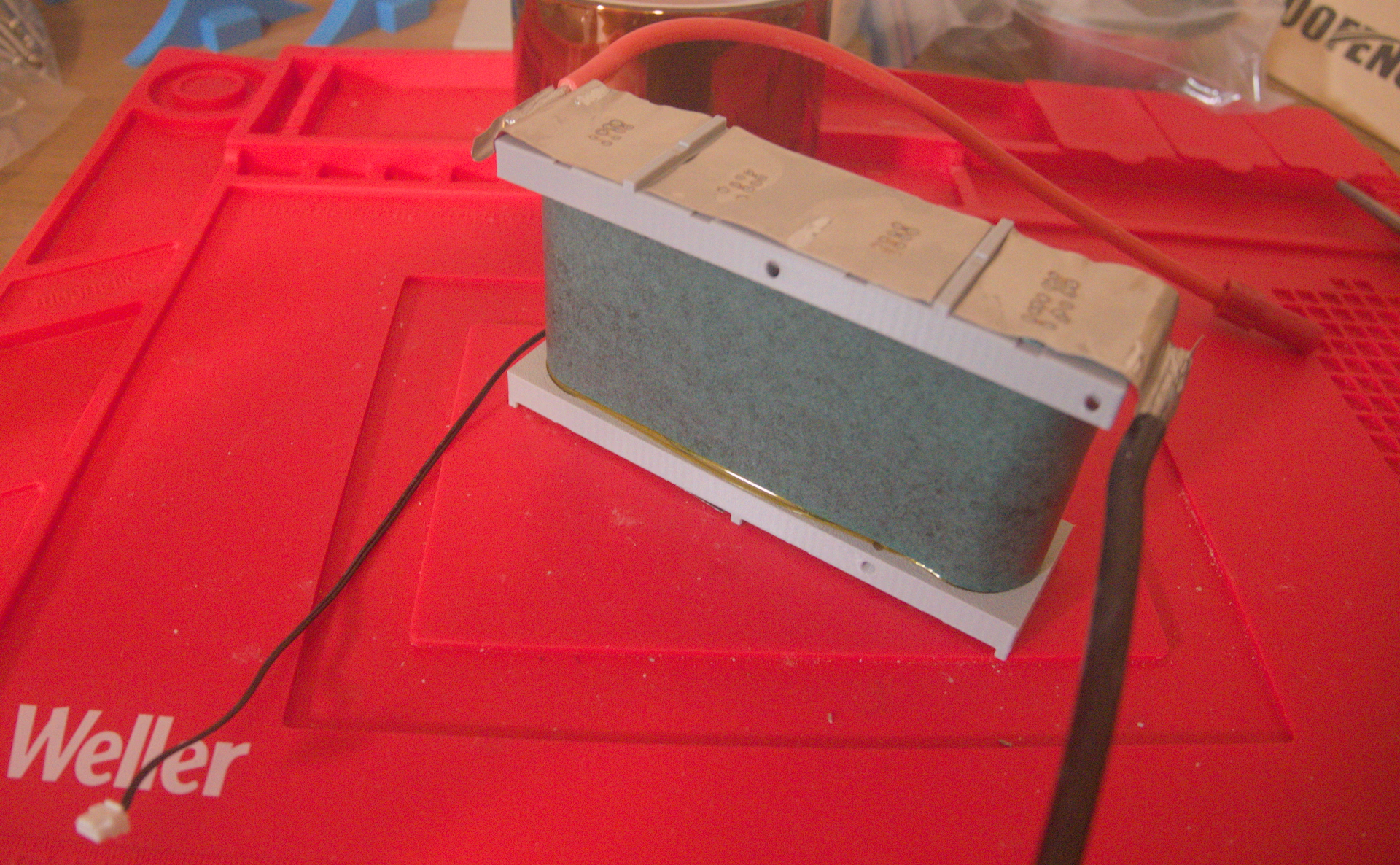
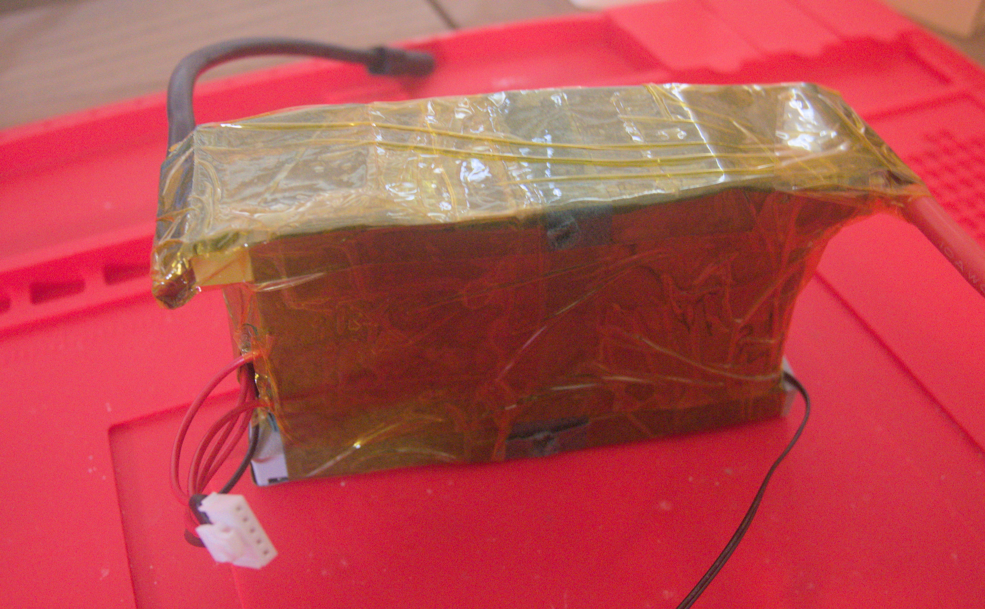
At this point, I no longer had a coherent plan, and it shows, because things got ugly. Not dangerous, just aesthetically displeasing. I started indiscriminately wrapping everything that looked slightly metallic in layers of fishpaper and Kapton tape.
In retrospect, I could have built out the cell holder a bit more to provide additional structure for the fishpaper, or even to replace it entirely to get more of a laptop battery look. I’ll probably take the whole thing apart at some point to do just that, but for now, I’m excited to have something that works!
Parts list
| Part | Model | Quantity | Price | Link | |
|---|---|---|---|---|---|
| Cell | Vapcell IFR26650 | 4 |
| ea. | Liion Wholesale |
| RC3563 |
| AliExpress | ||
| BMS | DALY H Series Standard BMS | 1 |
| AliExpress | |
| |||||
| Cell holder 3D model CC-BY-NC-SA-4.0 | 1 |
|
| ||
| |||||
| Fishpaper | ~5 m |
| AliExpress | ||
| |||||
| Fishpaper gasket | ~25 |
| AliExpress | ||
| |||||
| Nickel strip | ~2 m |
| AliExpress | ||
| |||||
| Kapton tape | ~33 m |
| AliExpress | ||
| |||||
| Wire | ~1 m | ||||
| |||||
| Wire | ~1 m | ||||
| |||||
| Bullet connector | Amass XT150 | ~10 |
| Amazon | |
| |||||
| Heat set insert | 2 |
| ea. | Amazon | |
| |||||
| Screw | 2 |
| ea. | Bolt Depot | |
| |||||
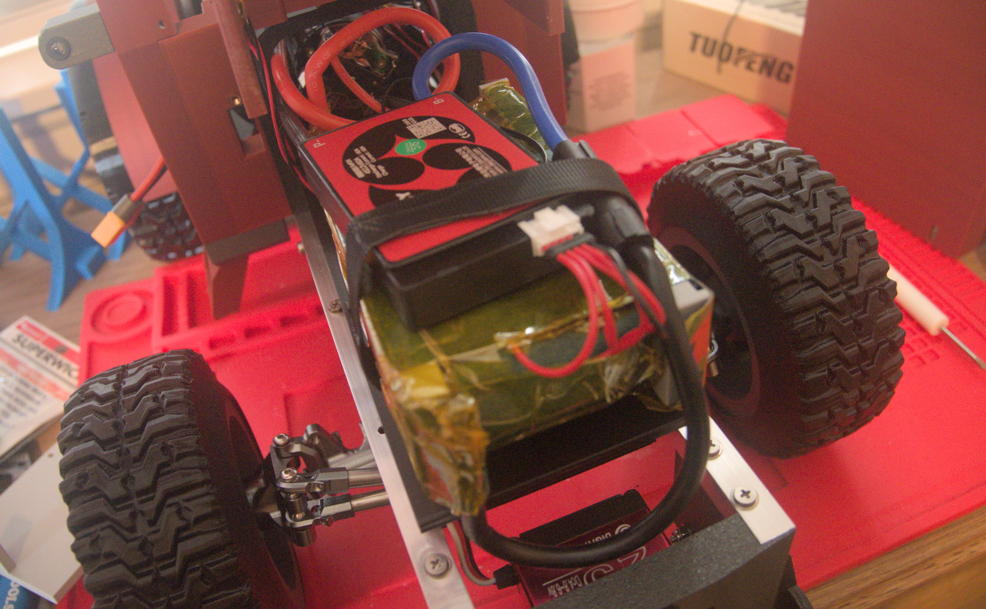
Conclusion
What’s that famous adage? “Measure twice, cut once.” Well, it doesn’t help when you deliberately modify the plan after you forgot what the constraints were. Adding the bracket and sled for the BMS made my battery too tall and it didn’t fit inside the tractor. So, for now, some velcro straps are doing the hard work of keeping everything roughly in place while I design a new hood.