Building and using the kWeld spot welder
- Confidence
- ●○○○○
- Domain experience
- ●○○○○
- Audience
- Battery junkies
- Summary
- I struggle to put together a spot welder kit.
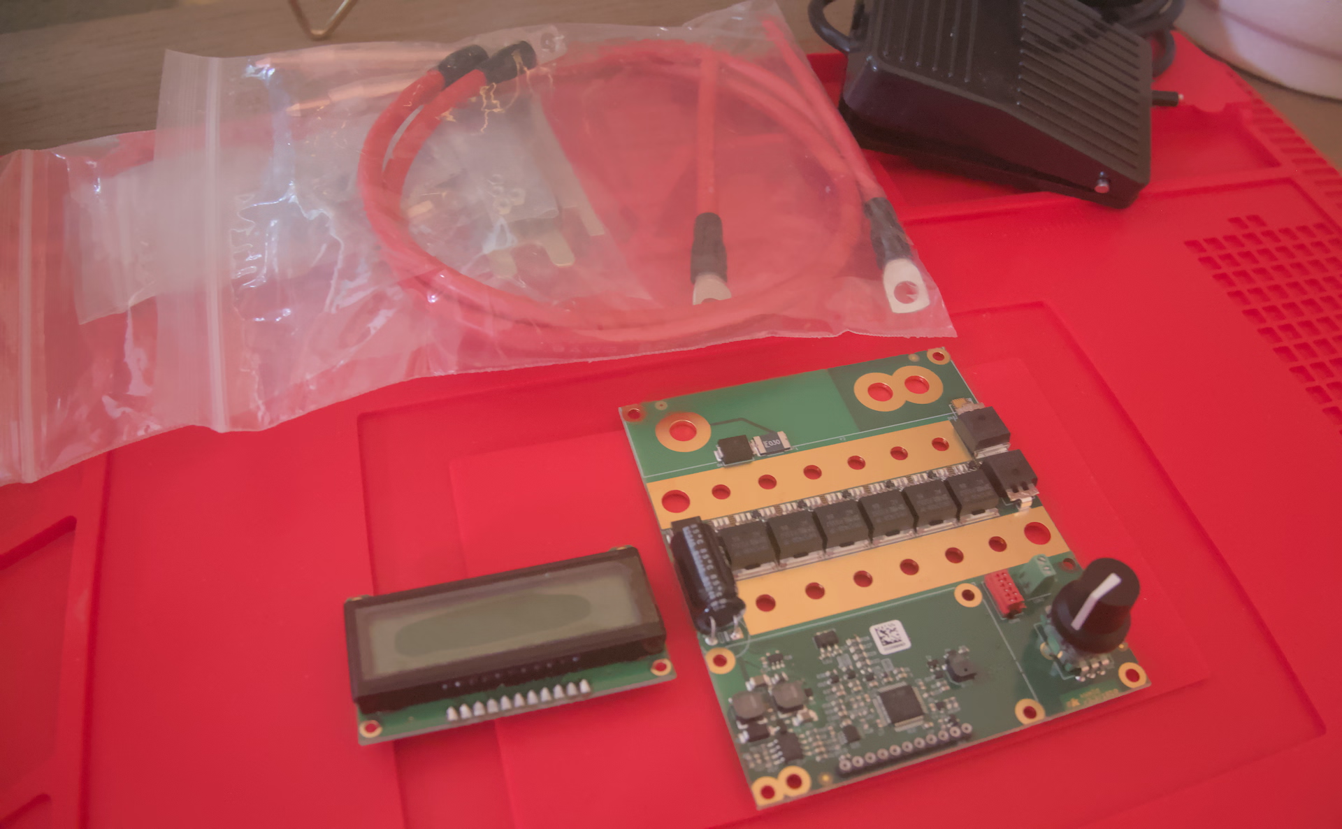
I bought the kWeld kit and the complementary kCap module to spot weld connections to cells. Both of these are boards with components pre-soldered, so they require a bit of assembly to be functional.
Preparation and other components
In addition to the kWeld and kCap boards, we’ll need a power supply and I’m really only comfortable operating this thing with a case. (I’m clumsy enough that just holding the electrodes is intimidating.)
You could buy a kSupply module; it’s designed to be attached to a server PSU, which you’d still have to buy separately (or have on hand, as more serious tinkerers seem to). The kCap documentation lists a few other options, including this MEAN WELL power supply, which is about half the price of the kSupply module by itself (but charges the capacitors more slowly). MEAN WELL supplies have worked for me in the past, so this feels like a good starting point.
Simultaneously, I found a very suitable case design published by a fellow named Oscar Olander. I had been thinking about making my own case anyway as I didn’t really like the design of the first-party kWeld or kCap cases (effectively still separate units, and no room for the power supply). This enclosure is even designed for the MEAN WELL unit.
I recommend printing the case before working on anything else as it is very useful to see how the parts will ultimately fit together. I printed it in PETG and it took about 7 hours.
Putting it together
Main module
We simply follow the assembly instructions from the kWeld manual. We don’t need to attach the standoffs for the main board.
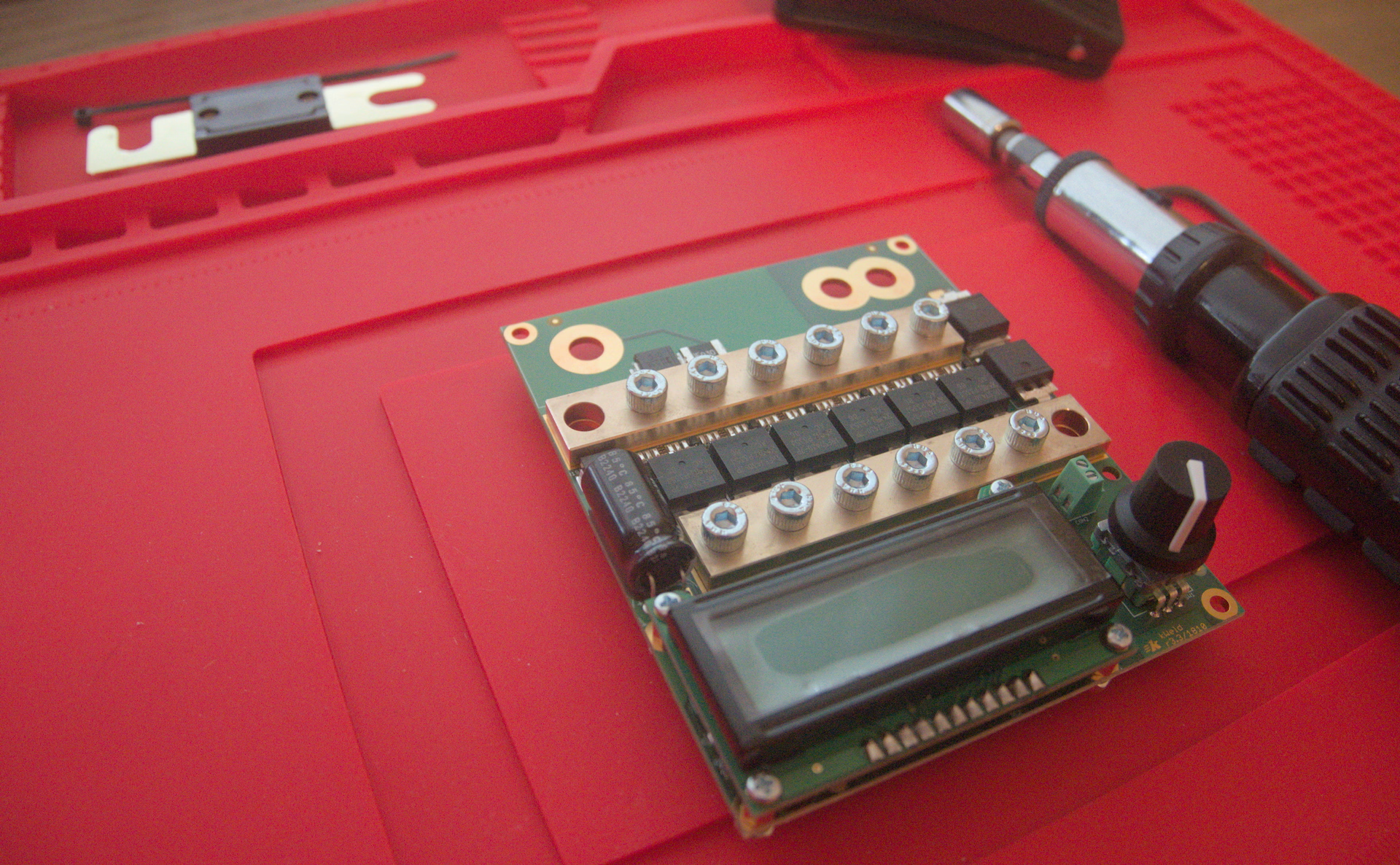
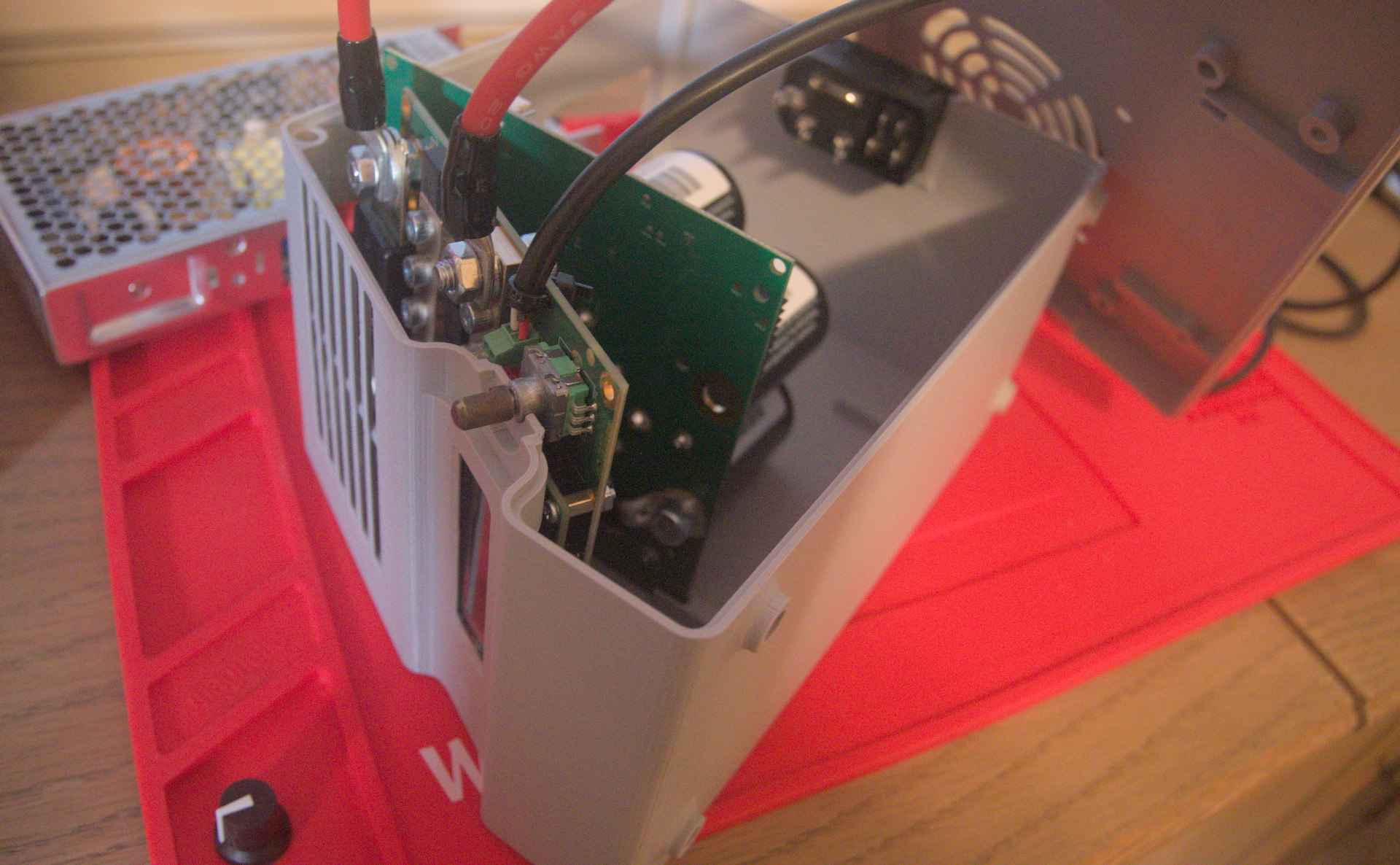
Rather than the unterminated wire from the kWeld kit, we use the wire with a ring terminal that came with the kCap. Also note the odd angle; this allows it to fit in the enclosure.
We connect the negative wires in a similar fashion.
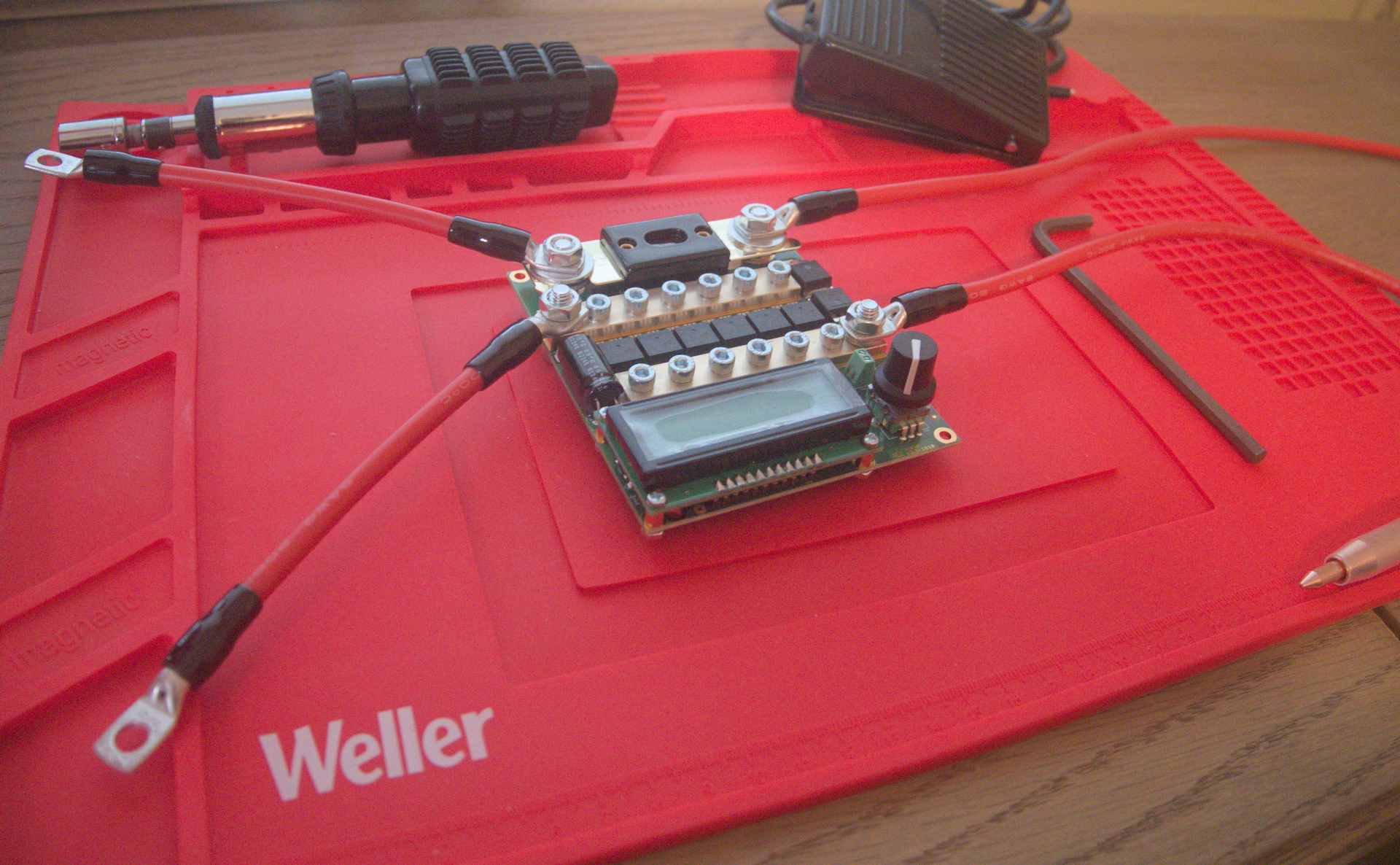
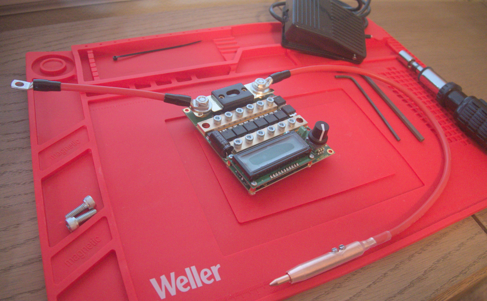
The wires for the foot switch need to pass through the case before we connect them to the terminal block.
You can take the electrodes off their cable assembly to pass them through the side of the case. The completed standalone kWeld module:
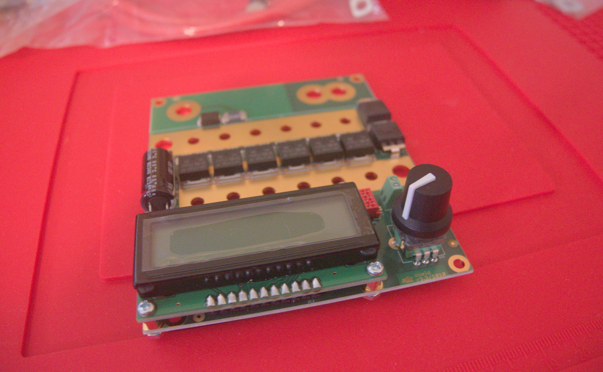
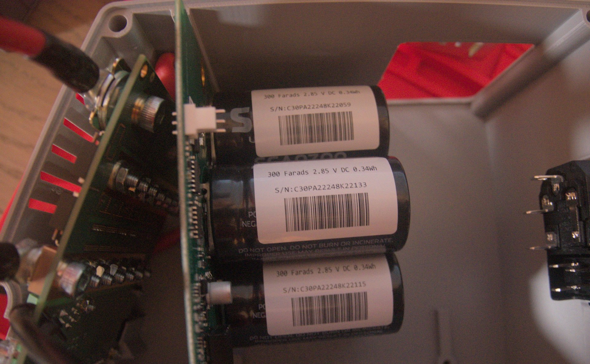
kCap
Follow the kCap manual to connect it to the kWeld. The output side of the kCap also needs wires at a weird angle to fit properly. Again, we don’t attach the standoffs.
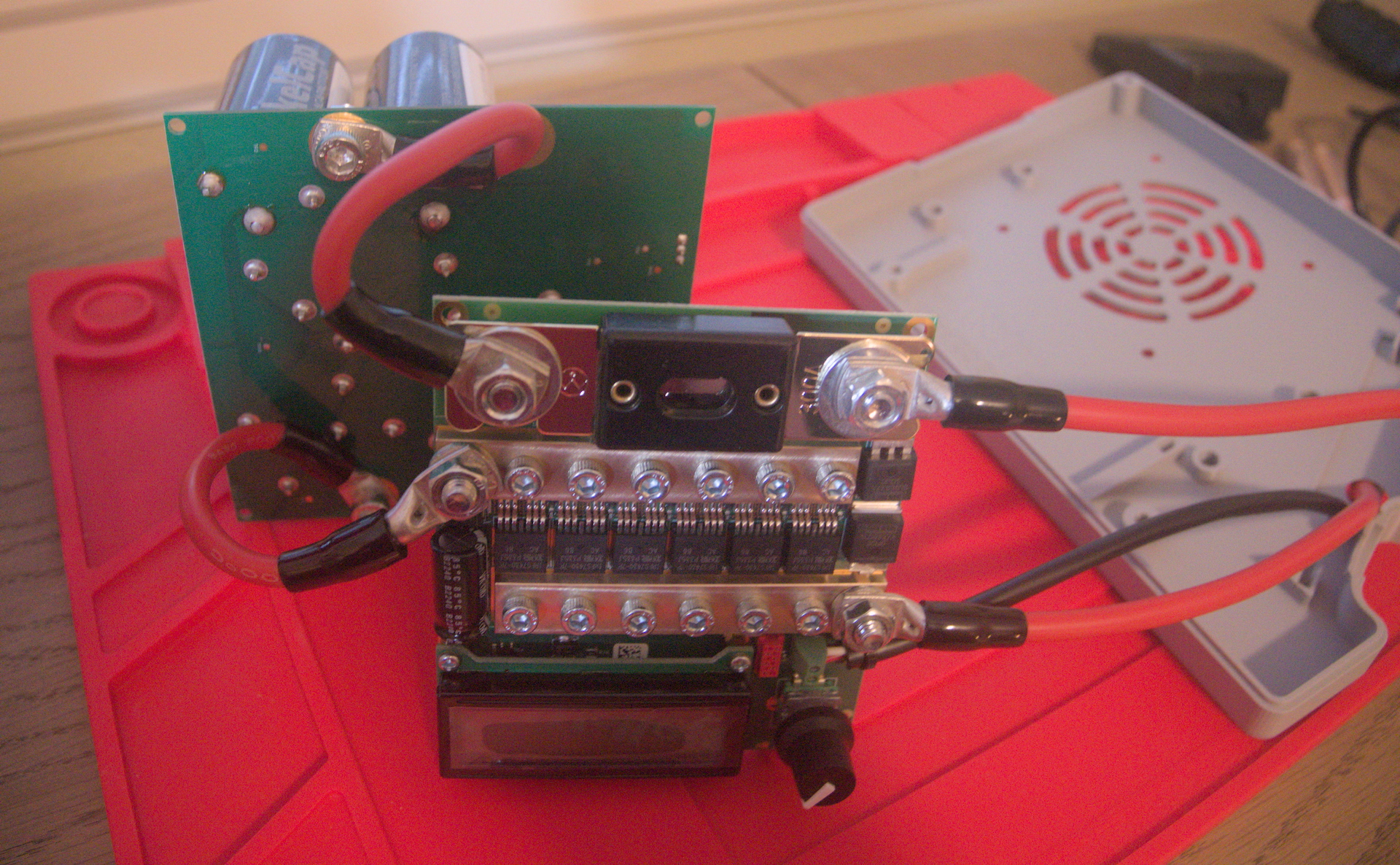
I tested the fit of the two boards in the case. It’s really tight. I thought I had done something very wrong until I realized I had to take the knob off the encoder. Then it went in with only slightly more effort than seemed appropriate.
Enclosure
I put the heat set inserts into the case. Two of them go on the left side to hold the top of the case together:
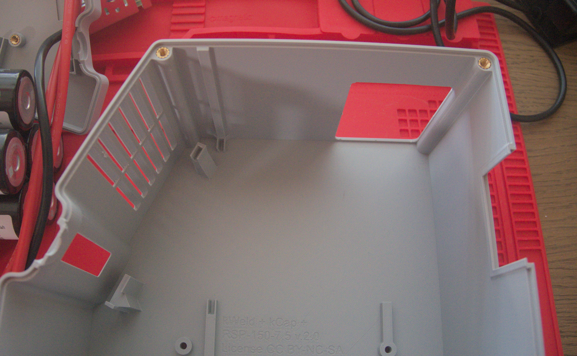
The other four are for “accessories” (for now, only an electrode holder). I inserted these from the inside of the right side. Unfortunately, when I did that, it melted the plastic and obscured the hole from the outside, so I had to do some additional cleanup.
Also, in retrospect, I probably should have done this step before I put a bunch of wires through the case. I had to hold the case awkwardly while I pushed the inserts in with the soldering iron.
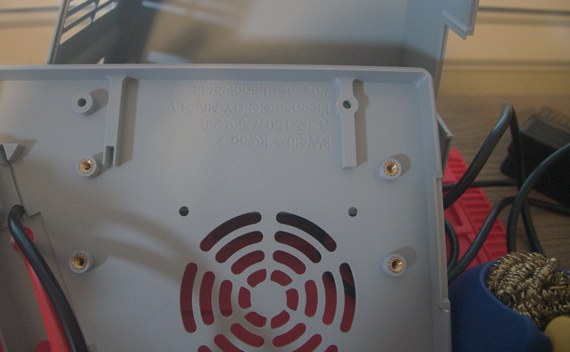
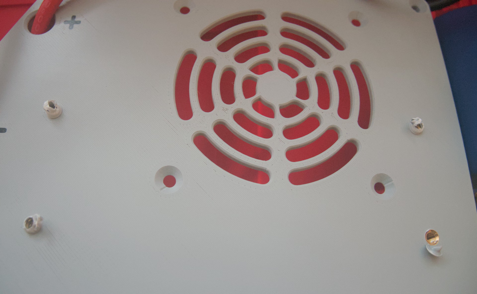

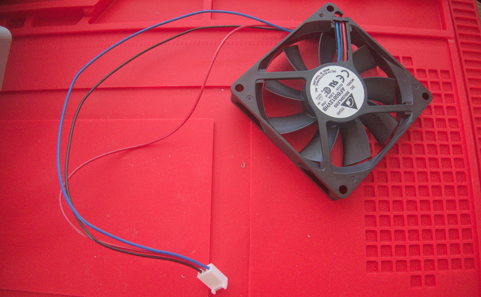
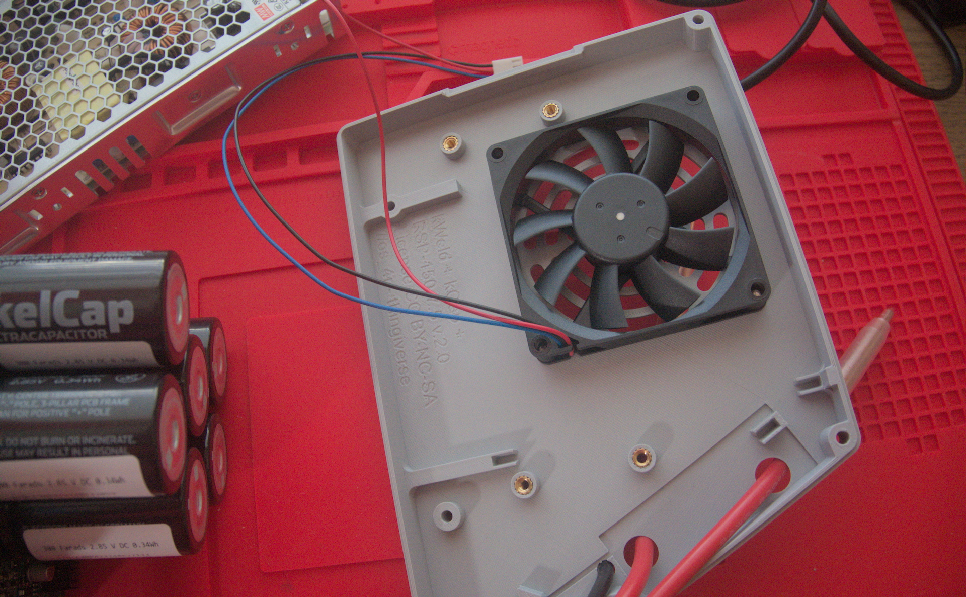
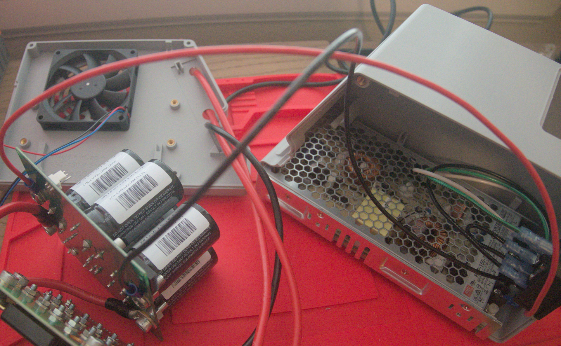
Case fan
The fan wires are unterminated, so I had to crimp them into Molex KK 254 terminals and insert them into a compatible housing. These are really small crimp terminals; I ended up buying (and would recommend) an Engineer PA-20 crimper for this step.
M5×10 mm screws, which are standard for case fans, work just fine for our application. The screw will bite into the fan frame.
Power supply
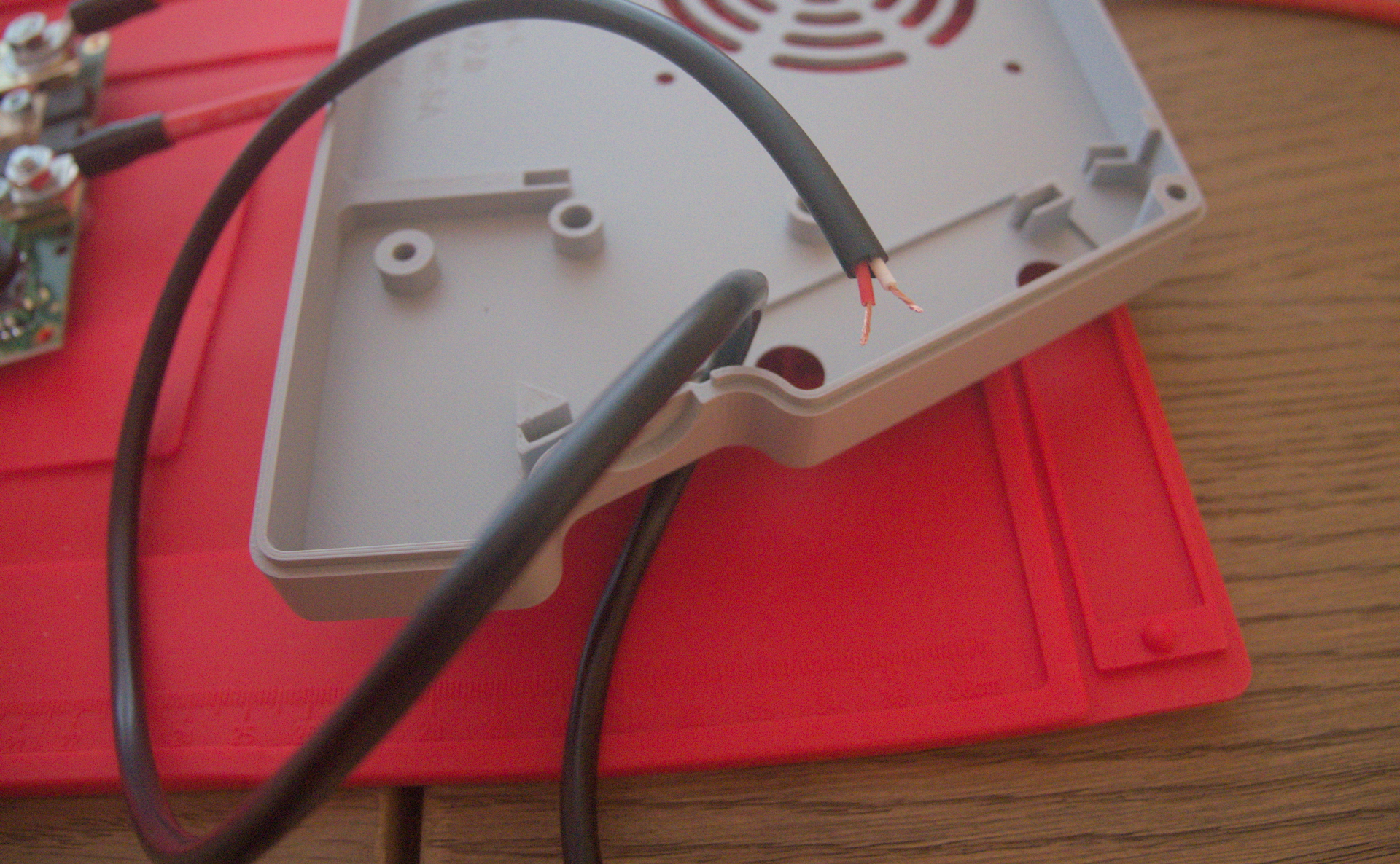
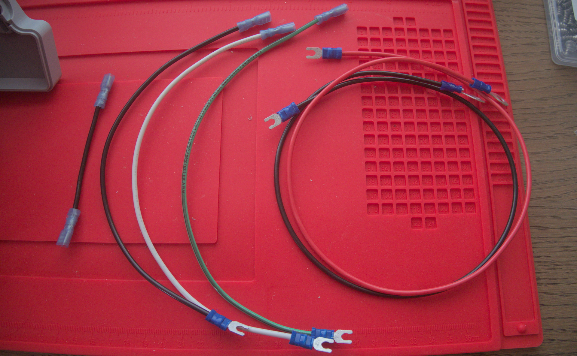
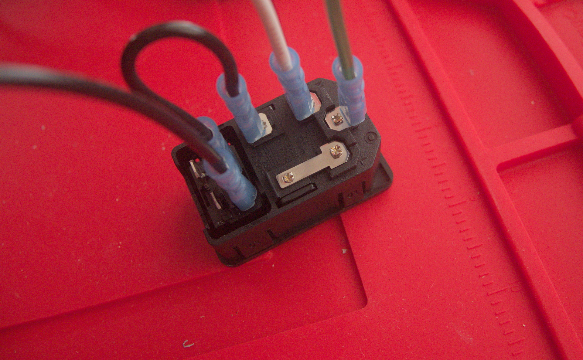
Next, I prepared the wires for the power supply assembly by cutting them to size and crimping them to the appropriate terminals.
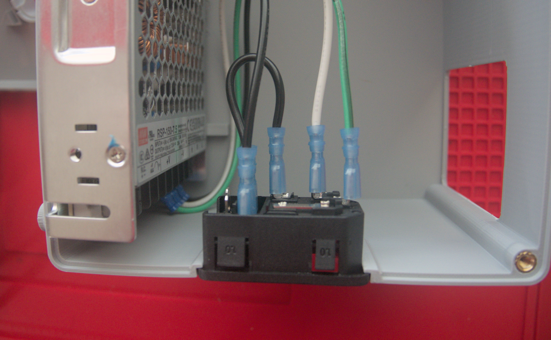
The power inlet has quick disconnect terminals, which I hadn’t used before. I initially bought these (apparently nice) TE Ultra-Fast terminals, but I didn’t realize the barrel had a flat side. That made it incompatible with my generic crimper, and I wasn’t in the mood to shell out hundreds of dollars for their magical proprietary crimper and die. I replaced the terminals with a different brand, but I still had a hard time aligning them; they also seemed to require a ton of force to close all the way.
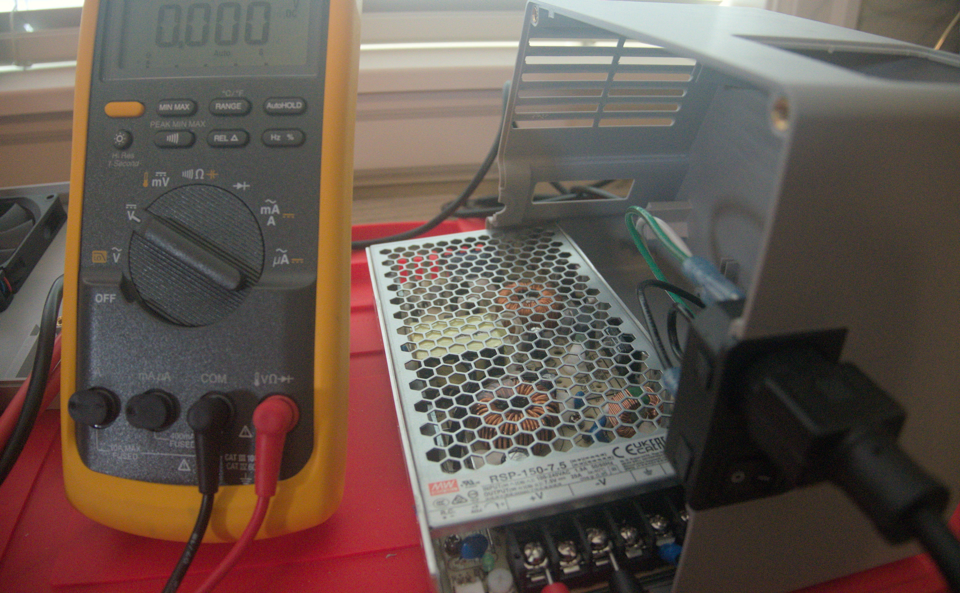
Nevertheless, the crimps turned out solid. How do I know? Well, I cut one open to see, but I also realized I could actually test the resistance of the wire because I had bought a microohmmeter from Aliexpress to check the internal resistance of my battery packs. Calibrated to American standards, these suckers will run you somewhere around
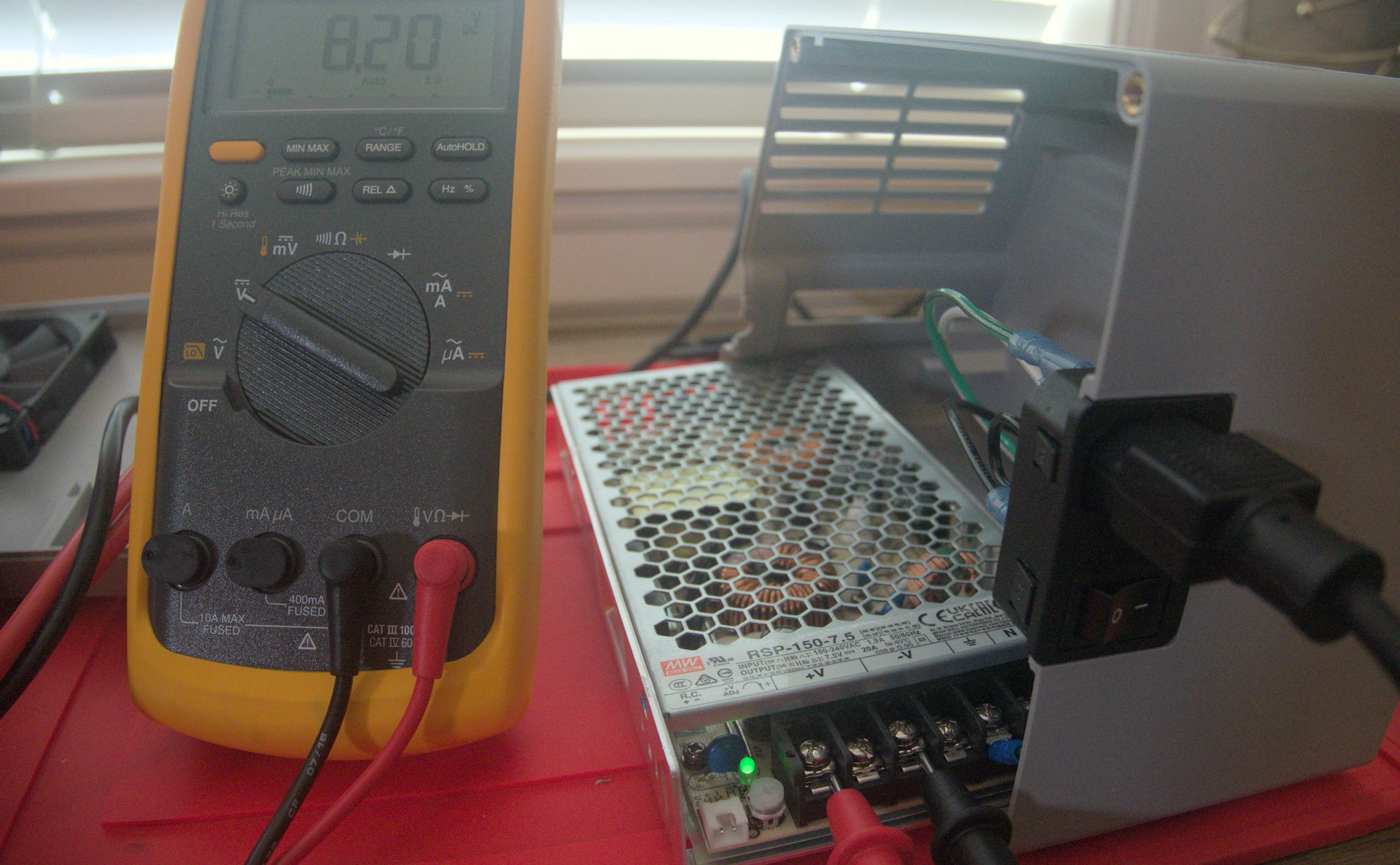
The kCap needs at least 8.1 V, so we use the adjustment pot on the PSU to select the proper output voltage before we connect it. The kCap documentation recommends 8.2 V for this PSU, so that’s what I set it to.
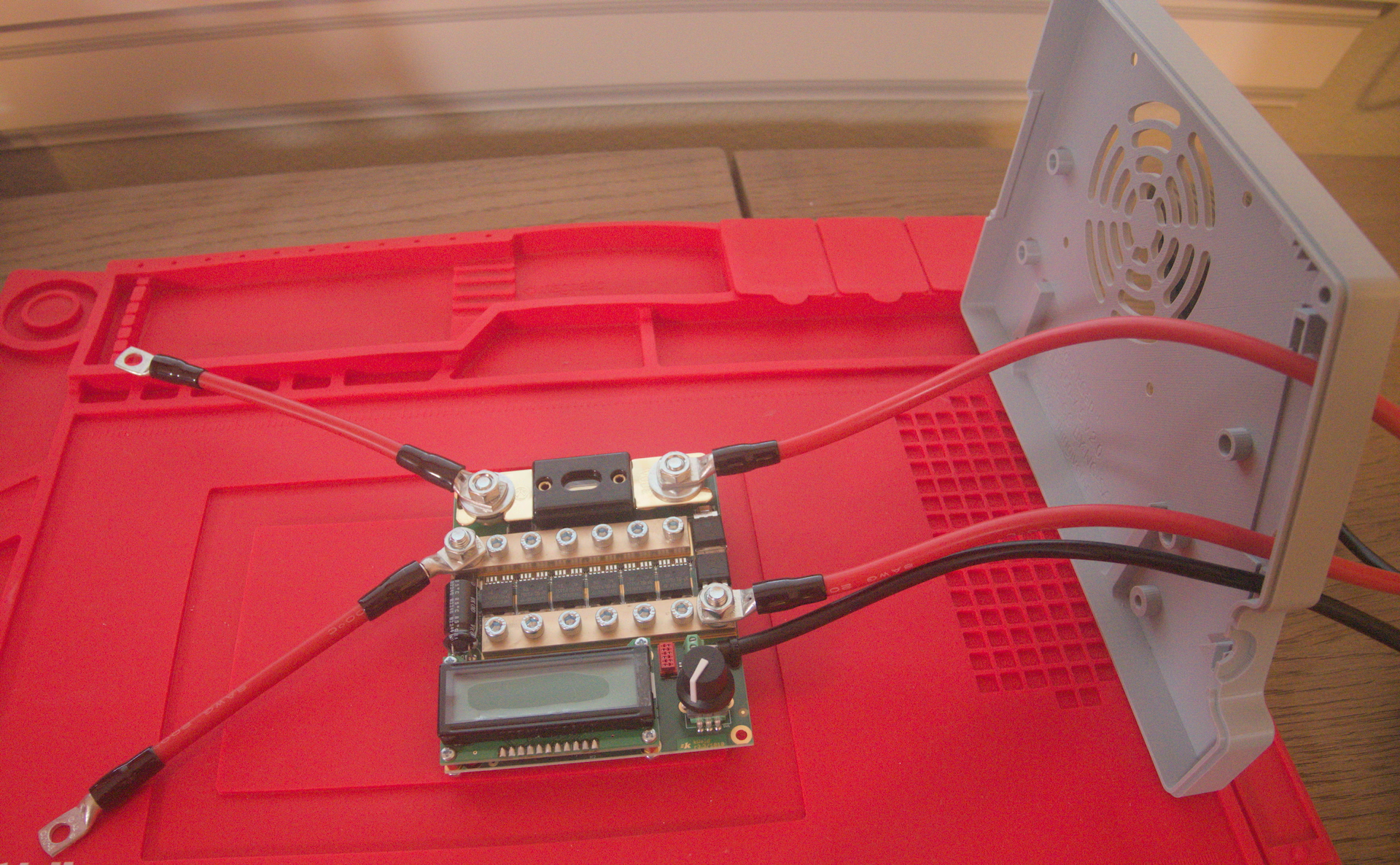
Fitment
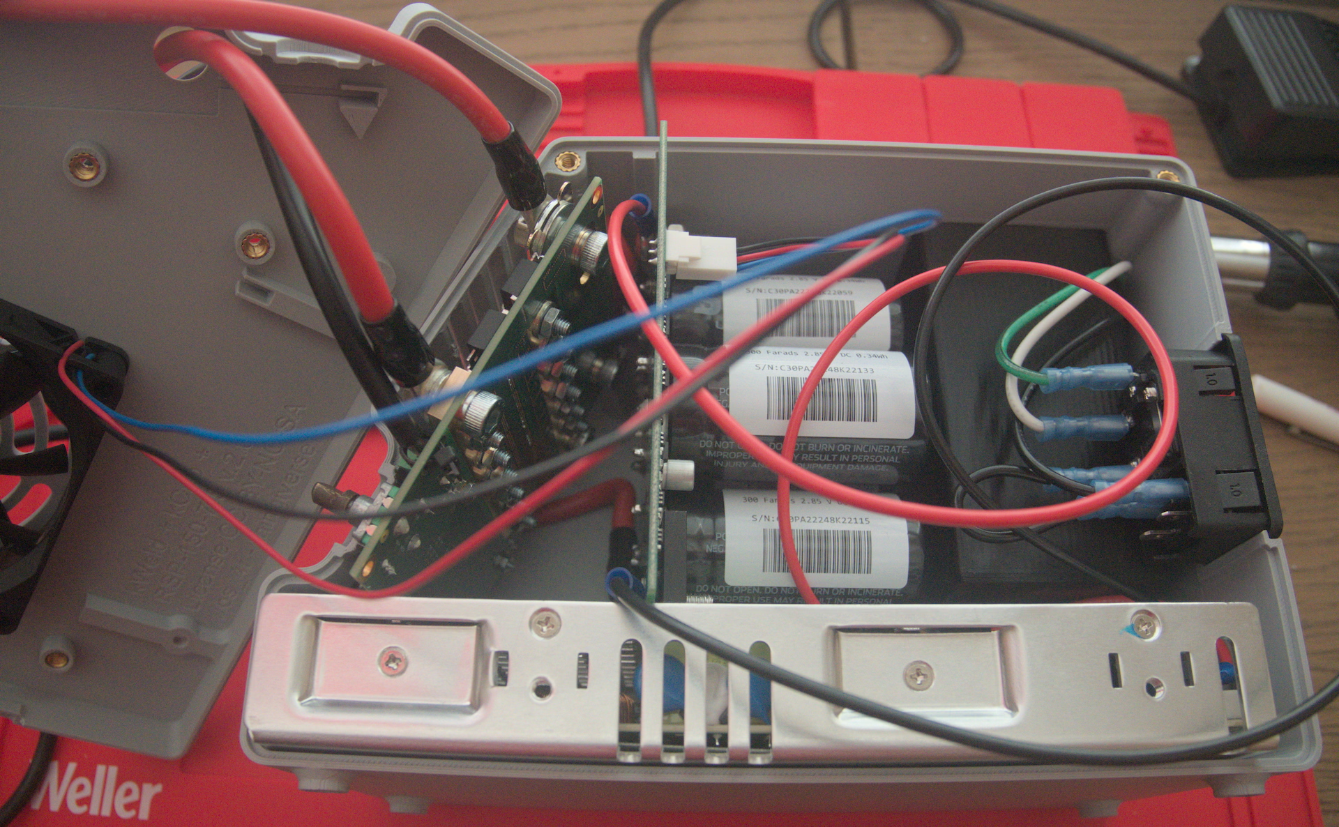
Finally, I put everything into the case together. Getting the right side of the case to fit onto the left side might have been the most difficult part of the entire project. In the test fit, you can see how the 6 AWG wire pushes the kCap away from its desired alignment. I ended up squishing the wire a bit to get the case to close; I’ll have to recheck everything after a few uses to make sure the screw for the kCap input isn’t damaging the insulation.
Speaking of that screw, I initially wired the input side of the kCap on the bottom of the board, just like the outputs. But there’s no space to run wires between the kCap and the PSU: the board is flush with the case on 3 sides and sitting on the PSU itself on the other side. So I ended up having to pull everything back out of the case to swap those connections to the top of the board instead.
The wires were also annoying to wrangle, and I ended up using some strategic zip ties to keep them together as appropriate. I pushed most of the AC wiring around the hole for the foot switch storage bucket.
If I were to rework the case a bit, I’d probably make it 5 mm–10 mm longer to increase the distance between the kWeld and kCap boards slightly. I’d also put some wire guides on the inside to help keep the DC and AC wires apart and everything away from the capacitors and the fan.
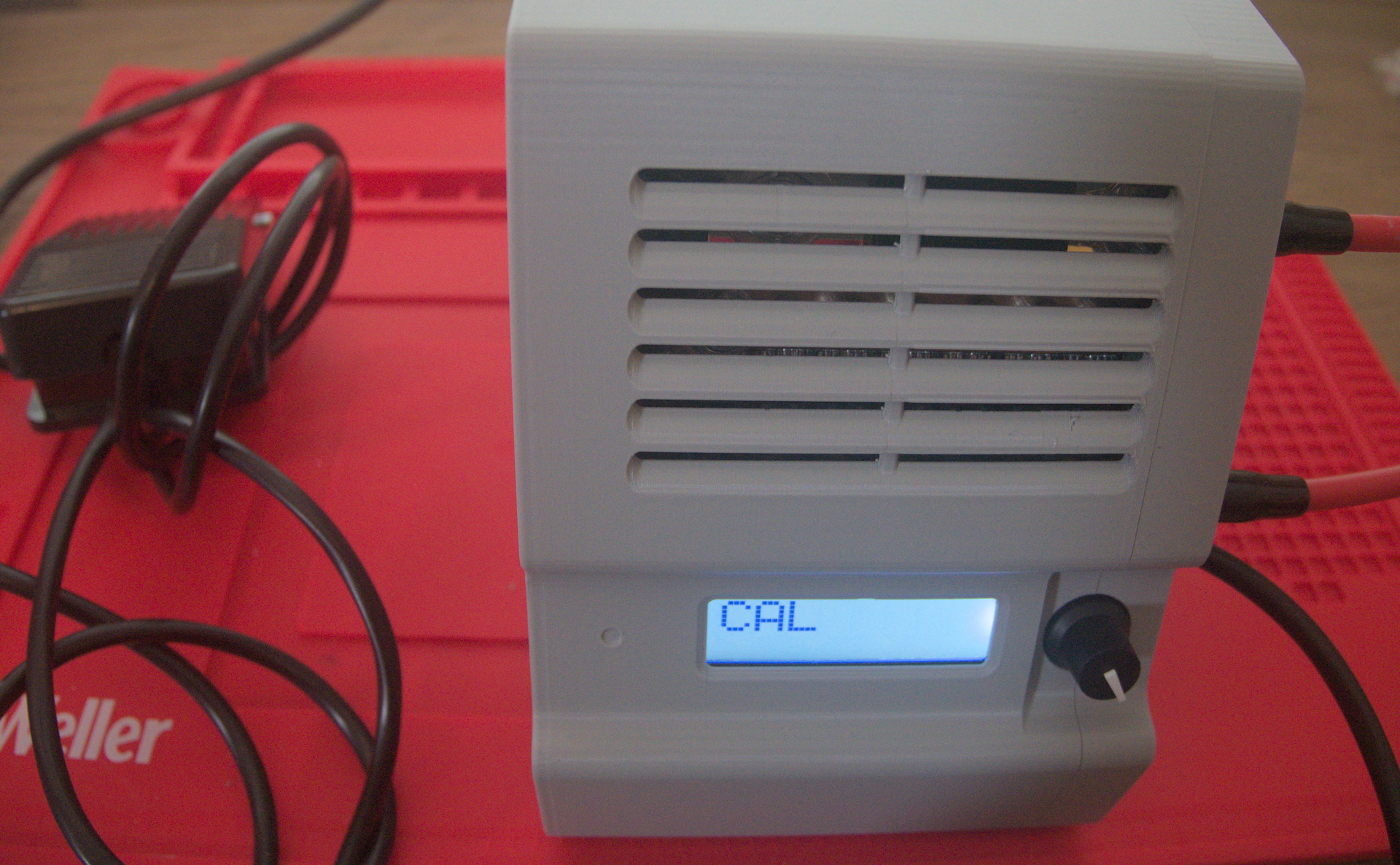
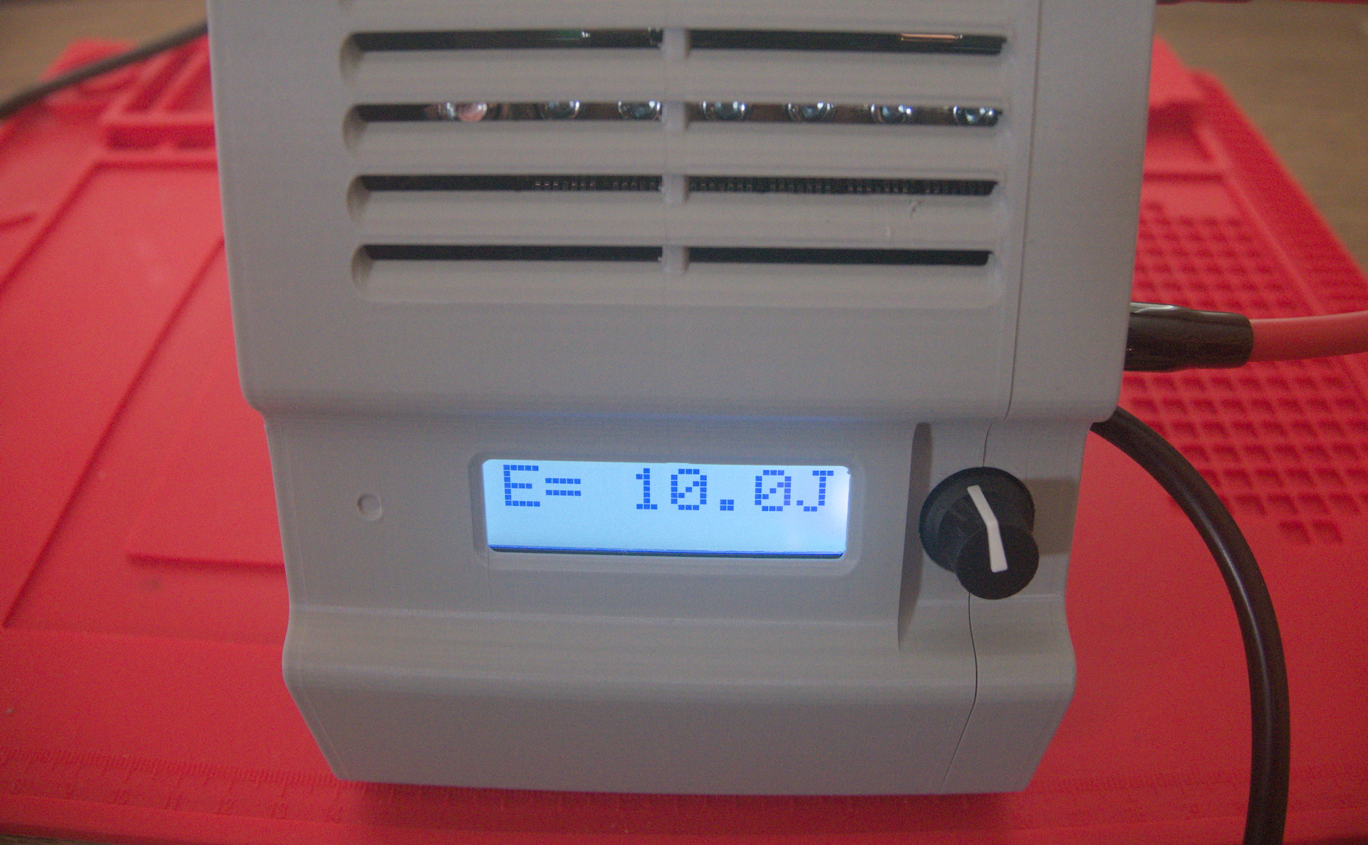
Following the calibration guide in the operation manual, I got about 1200 A from the kCap and about 2.8 mΩ for the internal resistance of the whole circuit, which is to spec. Now we’ll see if I need to buy another kCap to put in parallel or if my appetite will be fully sated by 0.2 mm-thick nickel strips.
Parts list
| Part | Model | Quantity | Price | Link | |
|---|---|---|---|---|---|
| Wire | ~1 m | ||||
| |||||
| Wire | ~1 m | ||||
| |||||
| Wire | ~1 m | ||||
| |||||
| Wire | ~1 m | ||||
| |||||
| Cable tie | ~5 | ||||
| Power supply assembly | |||||
| Power supply | MEAN WELL RSP-150-7.5 | 1 |
| DigiKey | |
| Inlet | Adam-Tech IEC-GS-1-100 | 1 |
| DigiKey | |
| Fuse | 1 |
| DigiKey | ||
| |||||
| Insulated quick disconnect terminal | 5 |
| ea. | Amazon | |
| |||||
| |||||
| kWeld assembly | |||||
| kWeld kit | 1 |
| Grid Rewired | ||
| kCap kit | 1 |
| Grid Rewired | ||
| Screw | 2 |
| ea. | Bolt Depot | |
| |||||
| Insulated ring terminal | 2 |
| ea. | DigiKey | |
| |||||
| |||||
| Washer | 2 |
| ea. | Bolt Depot | |
| |||||
| Hex nut | 2 |
| ea. | Bolt Depot | |
| |||||
| Case fan assembly | |||||
| Fan | Delta AFB0812VHB-F00 | 1 |
| DigiKey | |
| |||||
| Screw | 4 |
| ea. | Bolt Depot | |
| |||||
| Molex KK 254 crimp terminal | 3 |
| ea. | DigiKey | |
| Engineer PA-20 |
| Amazon | ||
| Molex KK 254 crimp housing | 1 |
| DigiKey | ||
| |||||
| Enclosure | |||||
| 3D model | 1 |
| Thingiverse | ||
| Heat set insert | 6 |
| ea. | Amazon | |
| |||||
| |||||
| Screw | 6 |
| ea. | Bolt Depot | |
| |||||
| Screw | 2 |
| ea. | Bolt Depot | |
| |||||
Conclusion
Happily, this turned out to be more like putting LEGO bricks together than a complex electronics project. Follow the instructions and you’ll be fine.
- Now let’s try to make a battery.